
System and method of operating a subsea module

a technology of subsea modules and subsea vehicles, applied in the field of subsea vehicles, can solve the problems of rov and tms, requires extensive logistics, takes several days or weeks to mobilize, etc., and achieves the effects of less space, improved logistics operations, and more rapid mobilization

Active Publication Date: 2020-09-08
OCEANEERING
View PDF10 Cites 1 Cited by
  • Summary
  • Abstract
  • Description
  • Claims
  • Application Information

AI Technical Summary

Benefits of technology

This system enhances mobilization efficiency, reduces costs and time, and minimizes space requirements, enabling rapid and cost-effective deployment of ROVs, AUVs, and ROTs by allowing self-contained operations with only electrical power and lifting equipment.

Problems solved by technology

This equipment, in addition to the ROV and the TMS, requires extensive logistics and often takes several days or weeks to mobilize to the intended location.

Method used


Image

  • System and method of operating a subsea module
  • System and method of operating a subsea module
  • System and method of operating a subsea module

Examples


Embodiment Construction

[0039]The following description will use terms such as “horizontal”, “vertical”, “lateral”, “back and forth”, “up and down”, “upper”, “lower”, “inner”, “outer”, “forward”, “rear”, etc. These terms generally refer to the views and orientations as shown in the drawings and that are associated with a normal use of the invention. The terms are used for the reader's convenience only and shall not be limiting.

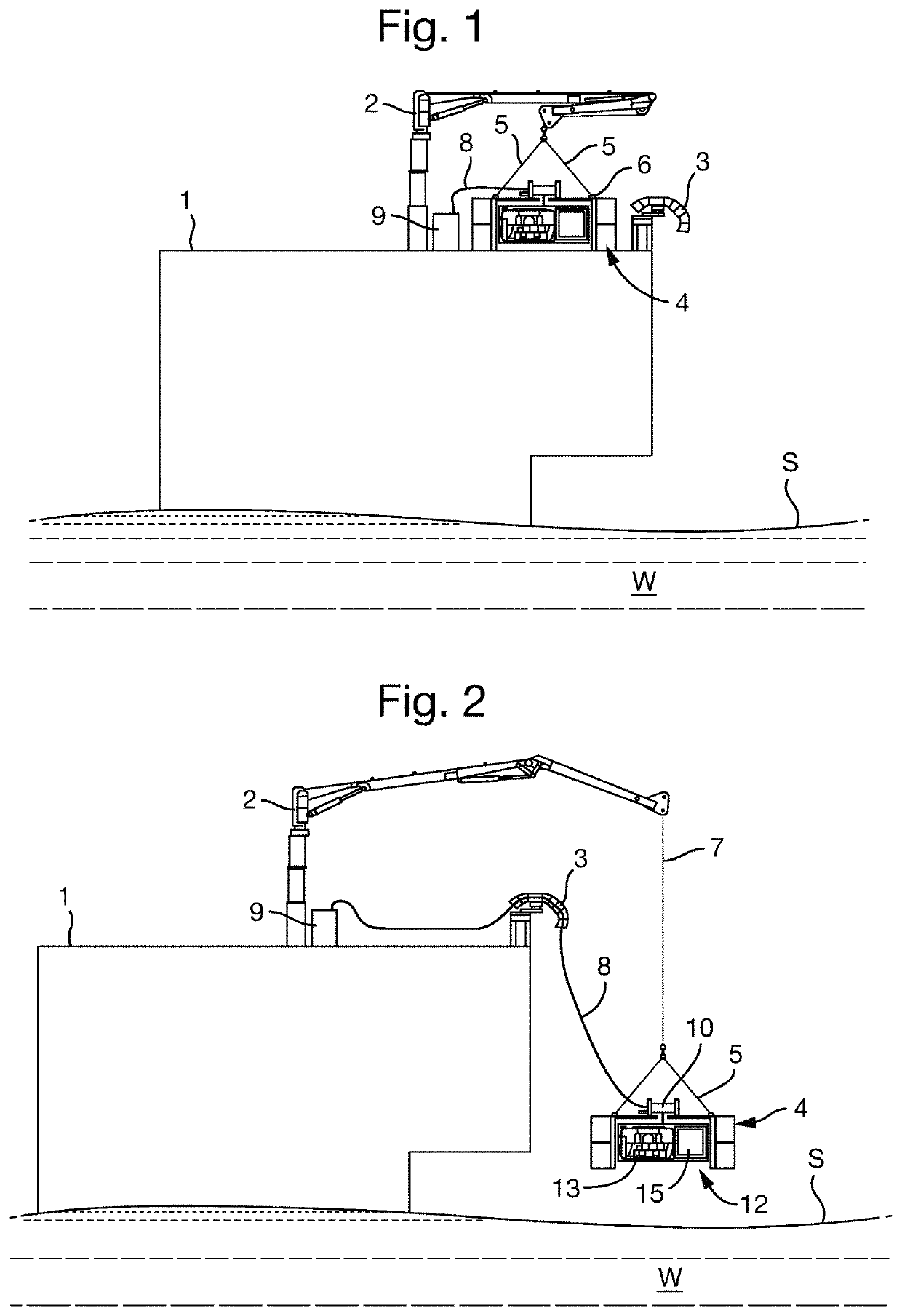
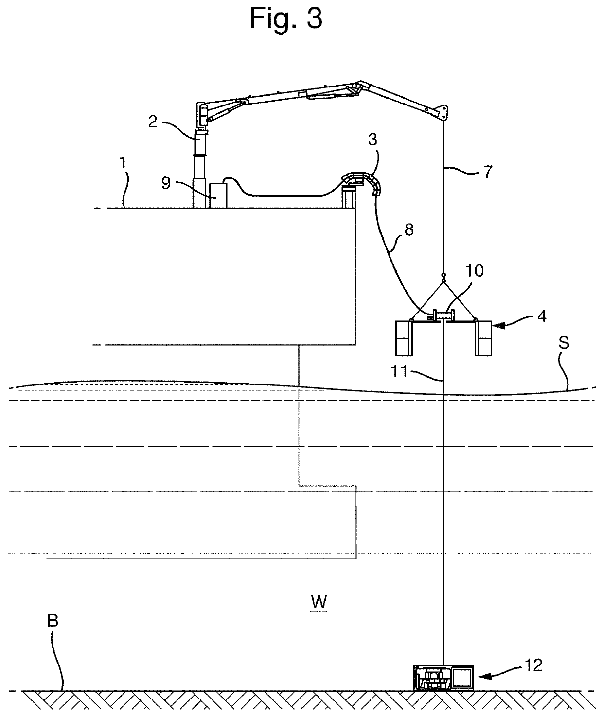
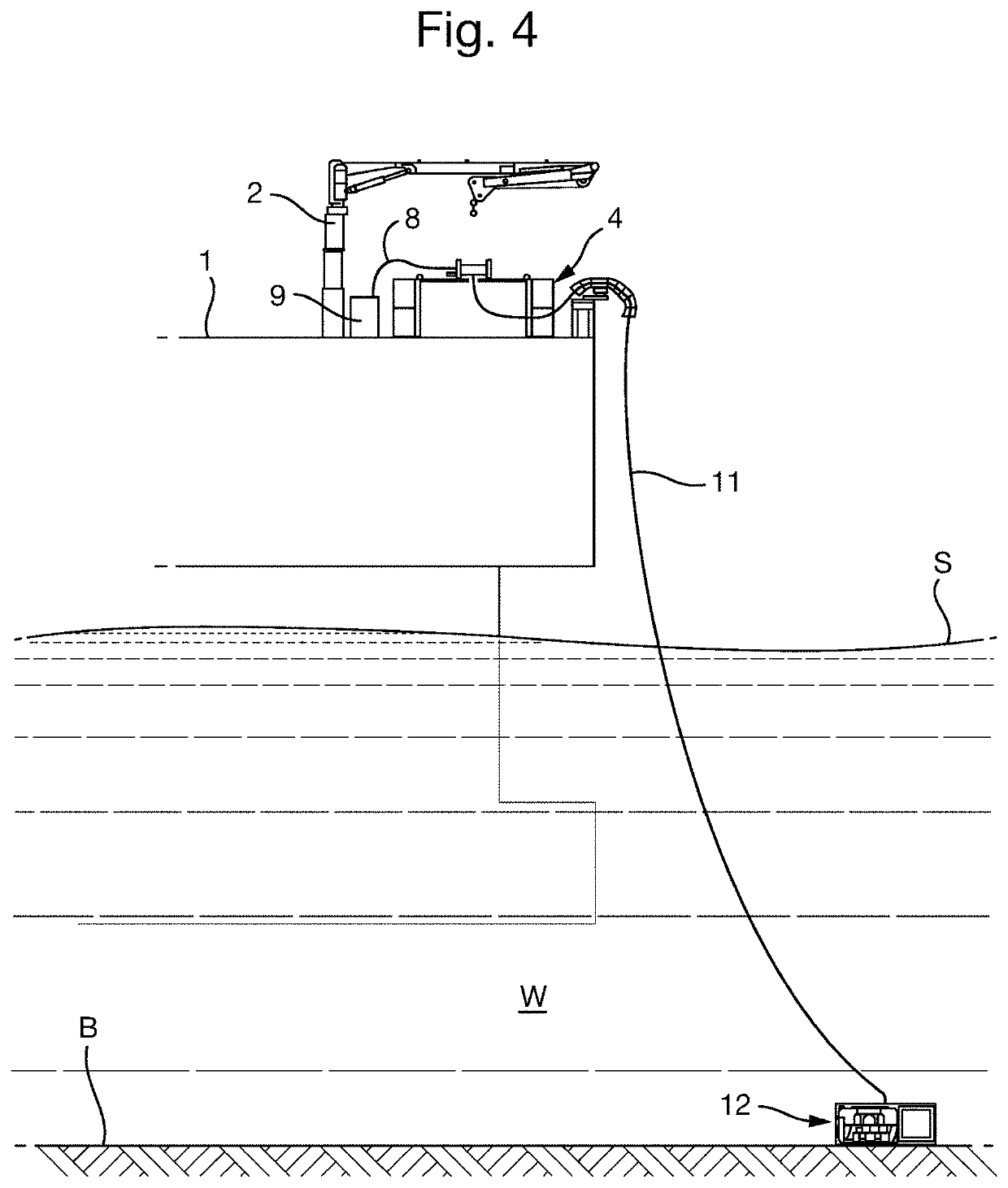
[0040]FIG. 1 shows an embodiment of the invented system, placed on the deck of a carrier structure 1. The carrier structure may for example be a ship, a floating platform, a fixed offshore, inshore or atshore installation, or a quay. The invented system comprises a deployment module 4, which is designated and configured for launching and recovering a subsea module, as will be described in the following. The term “deployment module” shall therefore not be limited to use only in a deployment operation, but also in a retrieval operation. The deployment module 4 is designed such that it ...


PUM


Abstract

A system for managing and controlling a subsea module is described herein. The system includes a deployment module configured to releasably receive and accommodate the subsea module and a load-bearing cable. One end of the load-bearing cable is connected to the subsea module and the other end is connected to a cable control device on the deployment module. The subsea module may be lowered out of and retracted into the deployment module. The subsea module may be configured to hold a subsea vehicle, such as a remotely operated vehicle or autonomous underwater vehicle. The subsea module may also be a remotely operated tool.

Description

CROSS-REFERENCE TO RELATED APPLICATIONS[0001]This application is a 35 U.S.C. § 371 National Phase of PCT Application No. PCT / NO2016 / 050240 filed Nov. 25, 2016, which claims priority to Norwegian Application No. NO 20160328 filed Feb. 26, 2016. The disclosures of these prior applications are hereby incorporated by reference herein.FIELD OF THE INVENTION[0002]The invention concerns the field of unmanned underwater vehicles. In particular, the invention concerns a system as set out by the preamble of claim 1, and a method of operating the system, as set out by the preamble of claim 13.BACKGROUND OF THE INVENTION[0003]Unmanned vehicles are widely used in underwater (also referred to as subsea) operations. Autonomous underwater vehicles (AUVs) and remotely operated vehicles (ROVs) are used for military operations, monitoring marine life, surveying seabed geology and archeology, salvage operations, as well as a multitude of tasks in connection with the extraction of hydrocarbons from subs...

Claims


Application Information

Patent Timeline
Patent Type & Authority Patents(United States)
IPC IPC(8): B63B27/16B63C11/52B66C23/52B63G8/00B63B27/10
CPCB63B27/10B63G8/001B66C23/52B63C11/52B63B27/16B63G2008/007B63B2027/165B63G2008/004B63G2008/008B63B27/36
Inventor HANSEN, RUNE
Owner OCEANEERING
Learn More