Eureka AIR delivers breakthrough ideas for toughest innovation challenges, trusted by R&D personnel around the world.

Wheel drive transmission

a technology of transmission and wheel drive, which is applied in the direction of gearing, couplings, transportation and packaging, etc., can solve the problems of complicated production and assembly of wheel drive, and achieve the effect of efficient and inexpensive production

Active Publication Date: 2020-09-08
AUBURN GEAR
View PDF51 Cites 2 Cited by
  • Summary
  • Abstract
  • Description
  • Claims
  • Application Information

AI Technical Summary

Benefits of technology

[0006]The present disclosure provides a multistage wheel drive including primary and secondary planetary stages, in which the ring gear of the primary (i.e., input-side) planetary stage is formed from a single machined part which also includes the planet gear carrier of the secondary (i.e., output-side) planetary stage. This dual-function “combination” component includes a splined exterior surface which interfaces with a correspondingly splined interior surface on the spindle in order to rotationally fix the combination component to the spindle. This arrangement ensures concentricity between the primary and secondary planetary stages, while allowing a desired amount of radial tolerance between the spindle, the combination component, and the hub of the wheel drive. In addition, the present arrangement can be produced efficiently and inexpensively.

Problems solved by technology

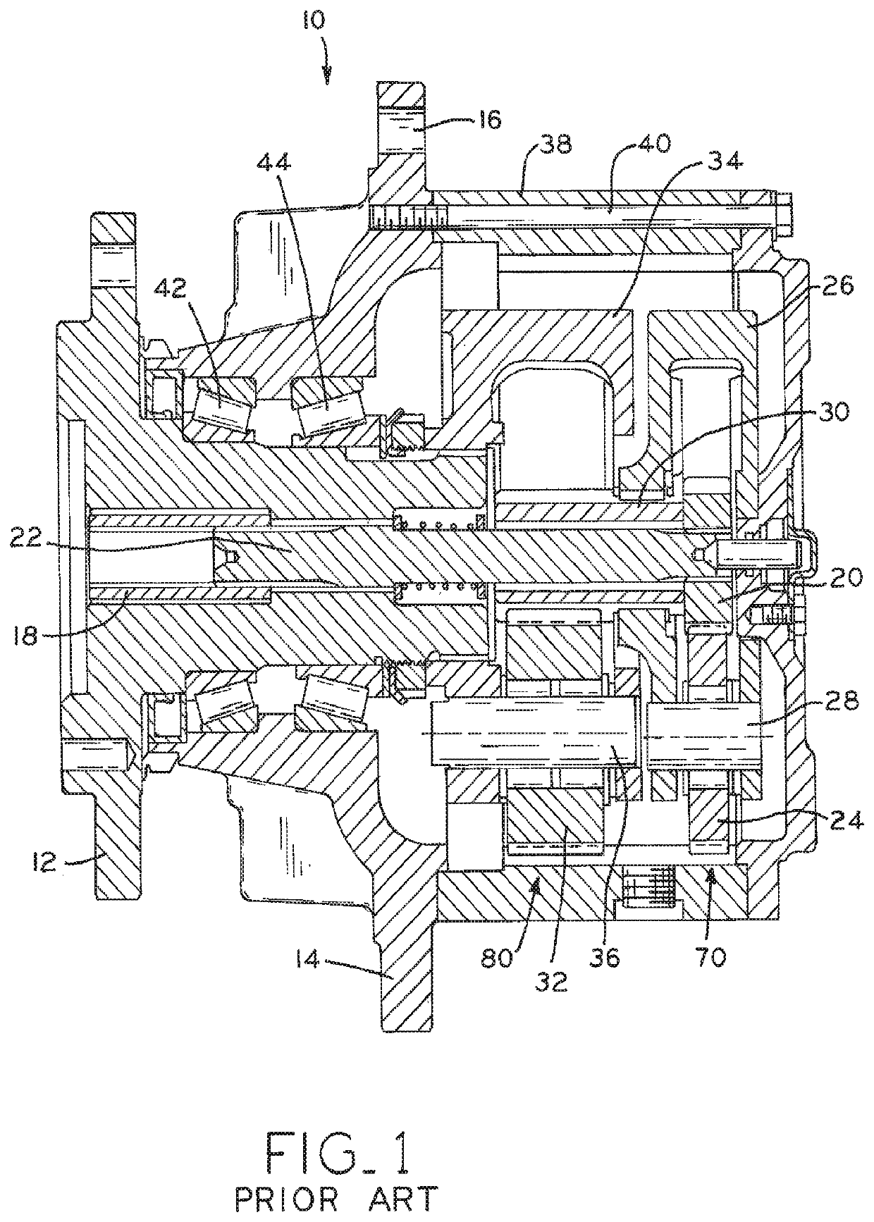
This monolithically formed spindle, ring gear and planet carrier is a large and complex part which may complicate the production and assembly of the wheel drive in some configurations.

Method used


Image

  • Wheel drive transmission
  • Wheel drive transmission
  • Wheel drive transmission

Examples


Embodiment Construction

[0030]As shown in FIGS. 11-14 wheel drive 310 includes hub 314 rotatably mounted to spindle 312, with a gear reduction system including primary stage 370 and secondary stage 380. Combination component 340 is a single, monolithic part incorporating one of the functional components of each stage 370, 380, thereby linking the two planetary stages 370, 380 to create planetary reduction assembly 360 as described in detail below. Combination component 340 also mounts to spindle 112 in a rotatably fixed configuration via splined connection 366, which provides some tolerance to allow for wear in roller bearings 342, 344 and also described further below.

[0031]Wheel drives 110, 210 are also described below, each including a monolithic spindle 112 and no analog to combination component 240. The features of wheel drives 110, 210 and 310 and interchangeable with one another, in that each individual feature of wheel drives 110, 210 or 310 may be incorporated into any of the other wheel drives 110...


PUM


Abstract

A multistage wheel drive includes primary and secondary planetary stages, in which the ring gear of the primary (i.e., input-side) planetary stage is formed from a single machined part which also includes the planet gear carrier of the secondary (i.e., output-side) planetary stage. This dual-function “combination” component includes a splined exterior surface which interfaces with a correspondingly splined interior surface on the spindle in order to rotationally fix the combination component to the spindle. This arrangement ensures concentricity between the primary and secondary planetary stages, while allowing a desired amount of radial tolerance between the spindle, the combination component, and the hub of the wheel drive. In addition, the present arrangement can be produced efficiently and inexpensively.

Description

CROSS-REFERENCE TO RELATED APPLICATIONS[0001]The present application is a national phase filing under 35 U.S.C. § 371 of International Patent Application No. PCT / US2016 / 047038, entitled “WHEEL DRIVE TRANSMISSION” and filed Aug. 15, 2016, the entire disclosure of which is hereby expressly incorporated by reference herein.BACKGROUND1. Technical Field[0002]The present disclosure relates to vehicle power transmission units, and, more particularly, to wheel-mounted gear reduction units.2. Description of the Related Art[0003]Wheel drives are used to provide gear reduction at or near the point of service, such as at the hub of a driven wheel. Wheel drives may be used for the large driven wheels commonly found on construction equipment and earth moving vehicles, for example, or for auger bits used in drilling post holes in the ground.[0004]International Patent Application Publication No. WO 2014 / 065851 describes a wheel drive arranged to provide a wide axial spacing between the internal bea...

Claims


Application Information

Patent Timeline
Patent Type & Authority Patents(United States)
IPC IPC(8): F16H1/46B60K17/04B60K17/08F16D1/10F16H3/66
CPCB60K17/046F16D1/10F16H1/46B60K17/04B60K17/08F16H3/66F16H2200/2007F16D2001/103
Inventor FORREST, JAMES L.JUHASZ, STEVE M.METZGER, DAN M.BEALS, JOSEPH A.
Owner AUBURN GEAR
Why Eureka
Eureka Blog
Learn More