
Depth generation system with adjustable light intensity

a technology of light intensity and depth generation system, which is applied in the field of depth generation system with adjustable light intensity, can solve the problems of eye damage, how to make the intensity of structured light changeable to prevent the eye damage of users, and the importance of so as to increase the quality of the depth map and reduce the power consumption of the depth generation system

Active Publication Date: 2020-09-01
EYS3D MICROELECTRONICS CO
View PDF22 Cites 0 Cited by
  • Summary
  • Abstract
  • Description
  • Claims
  • Application Information

AI Technical Summary

Benefits of technology

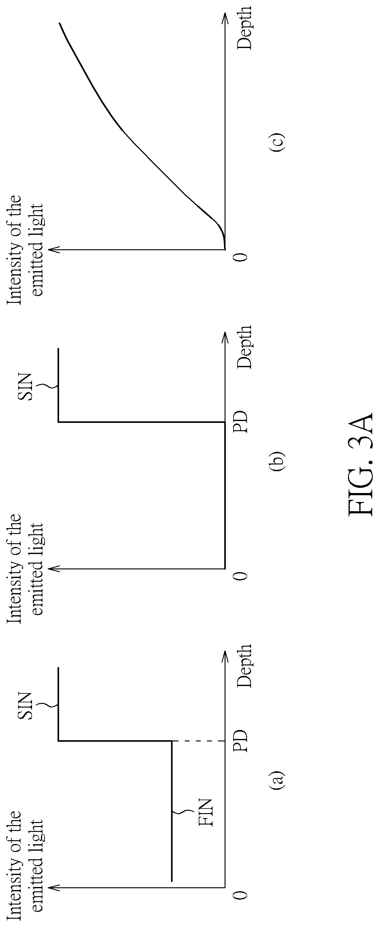
[0006]The present invention provides a depth generation system with adjustable light intensity. The depth generation system utilizes a controller to dynamically adjust intensity of emitted light generated by the depth generation system according to at least one of at least one depth of a depth map corresponding to at least one object, a proportion of invalid data of the depth map, intensity of at least one reflected light generated by the at least one object, and intensity of ambient light of an environment which the depth generation system is located at, compared to the prior art, the present invention can effectively prevent eyes of a user from being damaged, increase quality of the depth map, and reduce power consumption of the depth generation system.

Problems solved by technology

Although the luminance of the structured light in the maximum operating distance does not damage the eyes of the user, the eyes of the user may be damaged when the user is located within the maximum operating distance under the same power for making the luminance of the structured light in the maximum operating distance not damage the eyes of the user.
Because video and audio interactive devices that can interact with the user are gradually popular, how to make intensity of the structured light be changeable to prevent the eyes of the user from being damaged becomes an important issue.

Method used


Image

  • Depth generation system with adjustable light intensity
  • Depth generation system with adjustable light intensity
  • Depth generation system with adjustable light intensity

Examples


first embodiment

[0024]Please refer to FIG. 1. FIG. 1 is a diagram illustrating a depth generation system 100 with adjustable light intensity according to the present invention. As shown in FIG. 1, the depth generation system 100 includes a light source 102, an image capturer 104, a depth map generator 106, and a controller 108, wherein the depth map generator 106 is coupled to the image capturer 104 and the controller 108, and the controller 108 is further coupled to the light source 102. In addition, the present invention is not limited to the depth generation system 100 only including the light source 102 and the image capturer 104. That is, the depth generation system 100 can include a plurality of light sources and a plurality of image capturers. As shown in FIG. 1, the light source 102 is used for generating emitted light, wherein the emitted light is structured light, and the light source 102 can be a laser light source, a light emitting diode light source, a projector. In addition, taking a ...

second embodiment

[0033]In addition, please refer to FIG. 6. FIG. 6 is a diagram illustrating a depth generation system 600 with adjustable light intensity according to the present invention. As shown in FIG. 6, a difference between the depth generation system 600 and the depth generation system 100 is that the depth generation system 600 further includes an auxiliary device 602, wherein the auxiliary device 602 has a low power consumption characteristic and is not turned off by the controller 108. In addition, the auxiliary device 602 and the image capturer 104 form a second stereo camera, or the auxiliary device 602 and the image capturer 104 form a single point laser rangefinder. That is, the light source 102 and the image capturer 104 form a first depth generator, and the auxiliary device 602 and the image capturer 104 form a second depth generator (that is, the second stereo camera or the single point laser rangefinder). Therefore, because the auxiliary device 602 is not turned off by the contro...

third embodiment

[0036]In addition, please refer to FIG. 8. FIG. 8 is a diagram illustrating a depth generation system 800 with adjustable light intensity according to the present invention. As shown in FIG. 8, a difference between the depth generation system 800 and the depth generation system 100 is that the depth generation system 800 further includes a sensor 802, wherein the sensor 802 is used for sensing ambient light of an environment which the depth generation system 800 is located at, and the sensor 802 can be an RGB sensor or other type light sensors. Therefore, as shown in FIG. 9(a), when intensity of the ambient light is greater than the second predetermined intensity SPI and the intensity of the emitted light is the first intensity FIN, the controller 108 adjusts the intensity of the emitted light from the first intensity FIN to the second intensity SIN. That is, when the intensity of the ambient light is greater than the second predetermined intensity SPI and the intensity of the emitt...


PUM


Abstract

A depth generation system with adjustable light intensity includes at least one light source, at least one image capturer, a depth map generator, and a controller. Each light source of the at least one light source is used for generating emitted light. Each image capturer of the at least one image capturer is used for capturing an image including at least one reflected light generated by at least one object reflecting the emitted light. The depth map generator is coupled to the each image capturer for generating a corresponding depth map according to the image or the at least one reflected light. The controller is coupled to the depth map generator for determining whether to adjust intensity of the emitted light according to information of the corresponding depth map or intensity of the at least one reflected light.

Description

CROSS REFERENCE TO RELATED APPLICATION[0001]This application claims the benefit of U.S. Provisional Application No. 62 / 622,962, filed on Jan. 28, 2018 and entitled “Light Control System,” and the benefit of U.S. Provisional Application No. 62 / 681,683, filed on Jun. 7, 2018 and entitled “IMAGE PROCESSING METHOD AND SELF-CALIBRATION / LIGHT CONTROL METHOD FOR CAMERA DEVICE,” the contents of which are incorporated herein by reference.BACKGROUND OF THE INVENTION1. Field of the Invention[0002]The present invention relates to a depth generation system with adjustable light intensity, and particularly to a depth generation system that can utilize a controller to dynamically adjust intensity of emitted light generated by the depth generation system according to at least one of at least one depth of a depth map including at least one object (wherein the at least one depth corresponds to the at least one object), a proportion corresponding to invalid data in the depth map, intensity of at least...

Claims


Application Information

Patent Timeline
Patent Type & Authority Patents(United States)
IPC IPC(8): H04N13/271G01S17/89G06T7/521G01B11/25H04N5/235H04N5/232G06T7/593
CPCG01B11/2513G06T7/593H04N13/271H04N5/23206G06T7/521H04N5/2354G01S17/89H04N2213/007G06T2207/10012H04N13/296H04N13/204H05B47/105H04N23/54G01S17/10G01S17/931G01S17/894H04N13/254H04N23/74H04N23/661
Inventor LEE, CHI-FENGLU, HSUEH-JUNG
Owner EYS3D MICROELECTRONICS CO
Learn More