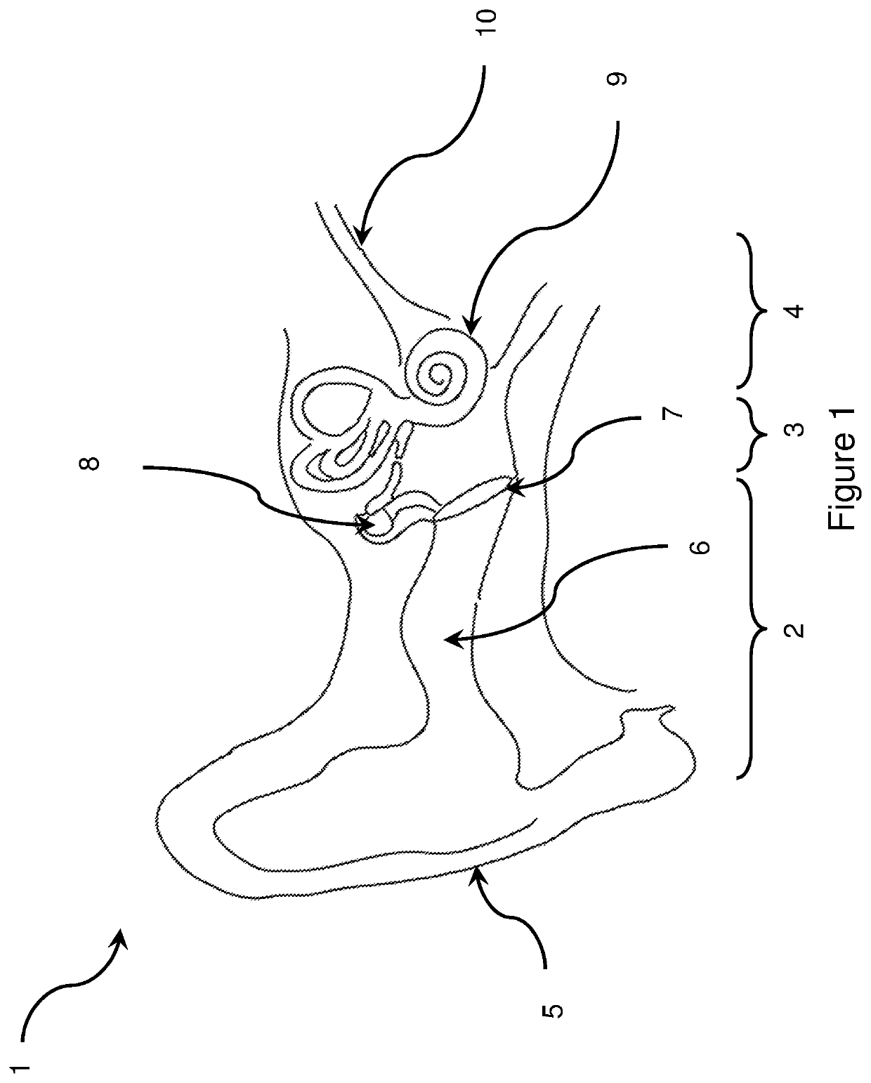
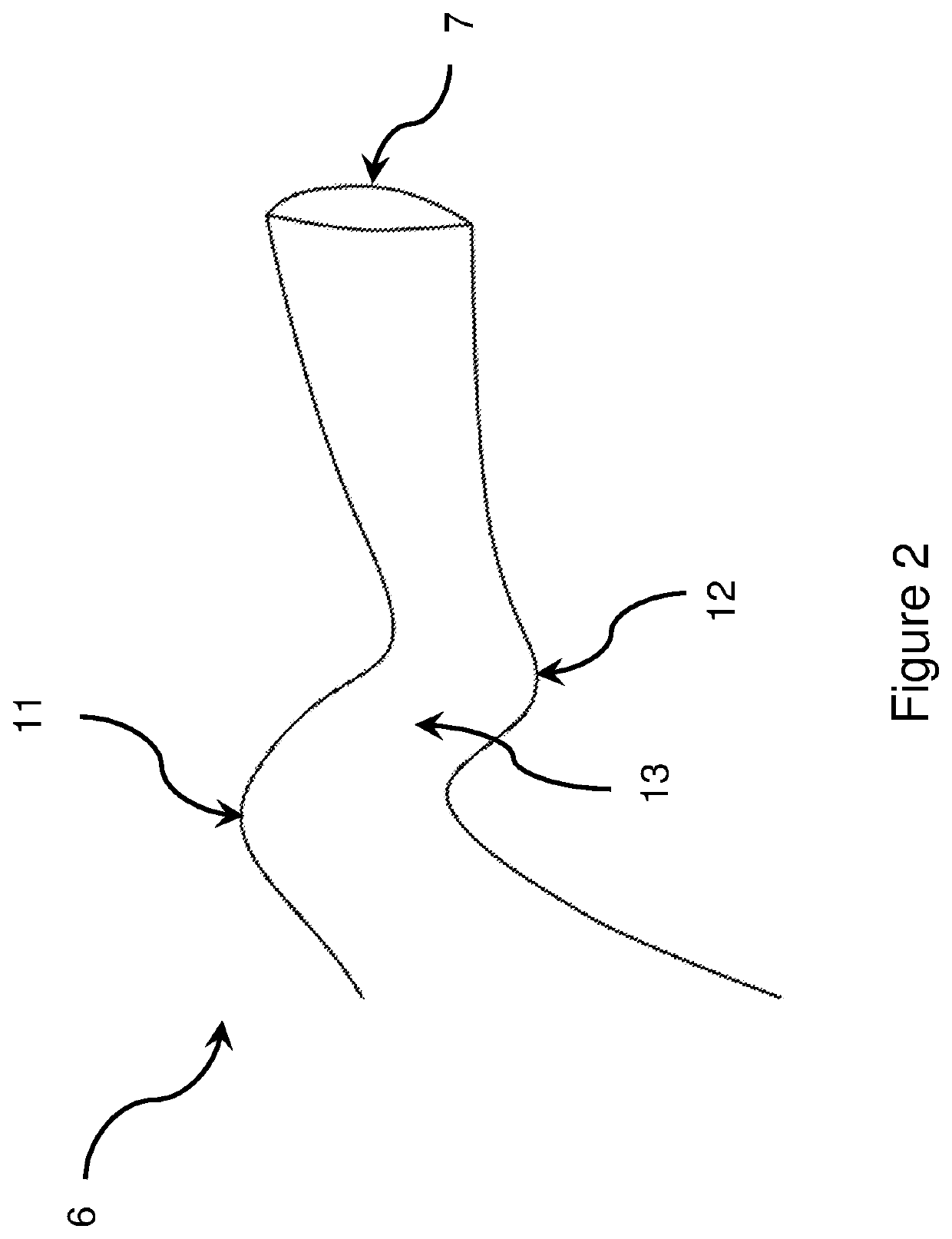
Earpiece having V-shaped interconnection between two portions of the earpiece when inserted into the ear canal
a technology of earpiece and ear canal, which is applied in the direction of earpiece/earphone manufacture/assembly, earpiece/earphone manufacturing/assembly, frequency/directions obtaining arrangements, etc., can solve the problems of consuming more power, affecting the earpiece, and affecting the earpiece. , to achieve the effect of minimising the loss of sound and optimising the biasing effect of the skir
- Summary
- Abstract
- Description
- Claims
- Application Information
AI Technical Summary
Benefits of technology
Problems solved by technology
Method used
Image
Examples
first embodiment
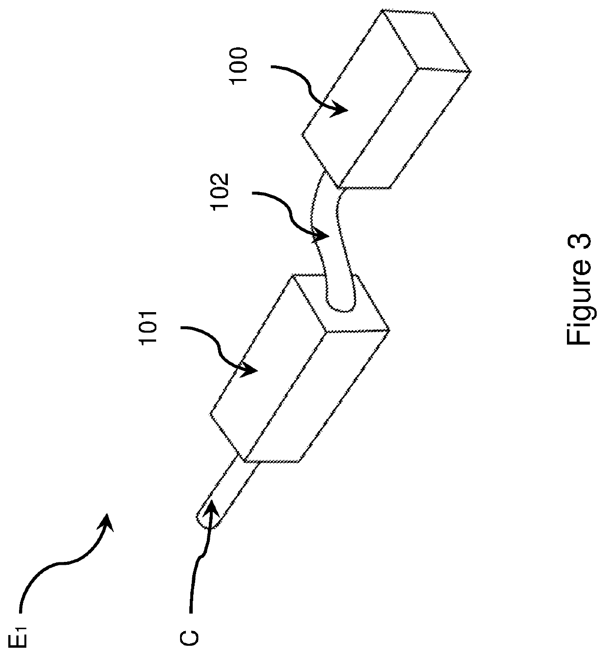
[0057]FIG. 3 depicts an earpiece in its most simple form. The earpiece E1 has an elongate body. The elongate body comprises a first portion 100 and a second portion 101 interconnected by a resilient bridge 102. The first portion 100, resilient bridge 102 and second portion 101 are arranged sequentially along the length of the elongate earpiece body. The first portion extends in a leading direction from the bridge and can otherwise be referred to as a “leading portion”.
[0058]The second portion extends in a trailing direction from the bridge and can otherwise be referred to as a “trailing portion”.
[0059]The earpiece body comprises a soft elastomeric material. The body is preferably encapsulated in an antimicrobial silver-ion treated silicon coating to provide waterproofing and biocompatibility.
[0060]The leading portion 100 and trailing portion 101 have a generally cuboid or ellipsoid shape. The leading portion 100 and trailing portion 101 are configured to house operational apparatus ...
fourth embodiment
[0085]As shown in FIGS. 8a to 8c, the earpiece E4 comprises a speaker 111 (e.g. a balanced armature driver) and associated outlet port 111a to project sound towards the tympanic membrane, a thermometer 112 to detect user temperature from the tympanic membrane or ear canal wall, a MEMS microphone 113 and associated inlet port 113a to detect ambient noise as part of a noise cancelling solution and a photoplethysmograph (PPG) heart rate monitor 114 and associated sensing ports 114a to detect a user heart rate. Power and electronic signals are transmitted to the operational apparatus of the earpiece via cables 115. The cables extend to the earpiece via connector C.
[0086]To provide sound enhancement and / or counter the leakage of low frequency sound in the ear canal (frequencies approximately 4 may comprise a piezoelectric actuator 115 to directly vibrate the middle ear so as to provide low frequency augmentation. The piezoelectric actuator may extend longitudinally in the leading portion...
fifth embodiment
[0087]FIGS. 9a and 9b depict the earpiece E5 where the first portion 1000, and second portion 1001 and resilient bridge 1002 are arranged to form a generally V-shaped body with a leading end and trailing end. The earpiece is configured to conform and be fully locatable in a user's ear canal. The leading end of the V-shaped body is configured to be positioned inwardly of the ear canal isthmus adjacent the tympanic membrane. The trailing end of the V-shaped body is configured to be positioned outwardly of the isthmus within the ear canal.
[0088]The V-shaped body comprises a soft elastomeric material. The body is preferably encapsulated in an antimicrobial silver-ion treated coating to provide waterproofing and biocompatibility.
[0089]As can be seen in FIGS. 9a and 9b, the resilient bridge 1002 forms the vertex at the leading end of the body, interconnecting the first portion and second portion. The first portion and second portion extend in a trailing direction from opposing ends of the...
PUM
 Abstract
Description
Claims
Application Information
 - R&D
- Intellectual Property
- Life Sciences
- Materials
- Tech Scout
- Unparalleled Data Quality
- Higher Quality Content
- 60% Fewer Hallucinations
Browse by: Latest US Patents, China's latest patents, Technical Efficacy Thesaurus, Application Domain, Technology Topic, Popular Technical Reports.
© 2025 PatSnap. All rights reserved.Legal|Privacy policy|Modern Slavery Act Transparency Statement|Sitemap|About US| Contact US: help@patsnap.com


