
Reflective electrode, method of manufacturing reflective electrode, and organic light emitting diode display including reflective electrode

a technology of reflective electrodes and reflective electrodes, which is applied in the direction of thermoelectric device junction materials, electrical apparatus, and semiconductor devices. it can solve the problems of difficult to improve the emission efficiency of oleds, and achieve the effect of improving the outcoupling efficiency

Active Publication Date: 2020-08-11
LG DISPLAY CO LTD
View PDF32 Cites 1 Cited by
  • Summary
  • Abstract
  • Description
  • Claims
  • Application Information

AI Technical Summary

Benefits of technology

[0007]The present disclosure provides a reflective electrode capable of improving outcoupling efficiency, a method of manufacturing the reflective electrode, and an organic light emitting diode (OLED) display including the reflective electrode.

Problems solved by technology

However, there was a difficulty in improving the emission efficiency of the OLEDs using an outcoupling technology because of limitation of the material itself.

Method used


Image

  • Reflective electrode, method of manufacturing reflective electrode, and organic light emitting diode display including reflective electrode
  • Reflective electrode, method of manufacturing reflective electrode, and organic light emitting diode display including reflective electrode
  • Reflective electrode, method of manufacturing reflective electrode, and organic light emitting diode display including reflective electrode

Examples


Embodiment Construction

[0025]Reference will now be made in detail to aspects of the disclosure, examples of which are illustrated in the accompanying drawings. Wherever possible, the same reference numbers will be used throughout the drawings to refer to the same or like parts. Detailed descriptions of known arts will be omitted if such may mislead the aspects of the disclosure. In describing various aspects, the same components may be described in a first aspect, and a description thereof may be omitted in other aspects.

[0026]The terms “first”, “second”, etc. may be used to describe various components, but the components are not limited by such terms. The terms are used only for the purpose of distinguishing one component from other components.

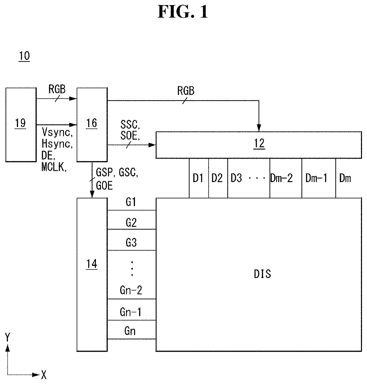
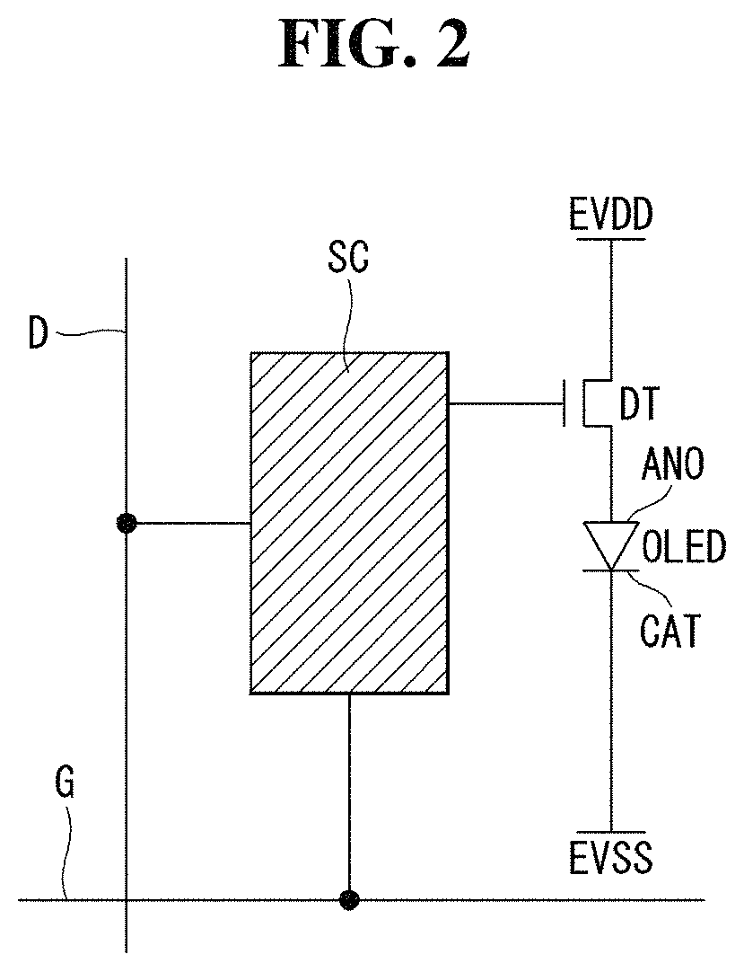
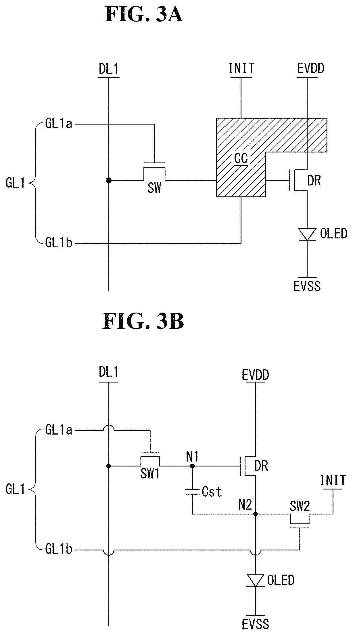
[0027]FIG. 1 is a block diagram schematically illustrating an organic light emitting diode (OLED) display according to an aspect of the disclosure. FIG. 2 schematically illustrates configuration of a pixel shown in FIG. 1. FIGS. 3A and 3B illustrate in detail examp...


PUM

PropertyMeasurementUnit
temperatureaaaaaaaaaa
transparent conductiveaaaaaaaaaa
transparentaaaaaaaaaa

Abstract

A reflective electrode, a method of manufacturing the reflective electrode, and an organic light emitting diode display including the reflective electrode are disclosed. The reflective electrode includes a first transparent conductive layer formed of a transparent conductive material, a reflective layer disposed on the first transparent conductive layer and including a plurality of grains formed of a reflective material, and a second transparent conductive layer disposed on the reflective layer and formed of a transparent conductive material. The adjacent grains are spaced from each other.

Description

CROSS REFERENCE TO RELATED APPLICATION[0001]This application claims the priority benefit of Korean Patent Application No. 10-2017-0128232 filed on Sep. 29, 2017, which is incorporated herein by reference for all purposes as if fully set forth herein.BACKGROUND OF THE DISCLOSUREField of the Disclosure[0002]The present disclosure relates to a reflective electrode, a method of manufacturing the reflective electrode, and an organic light emitting diode display including the reflective electrode.Description of the Background[0003]Various display devices have replaced heavy and bulky cathode ray tubes (CRTs). Examples of the display devices include a liquid crystal display (LCD), a field emission display (FED), a plasma display panel (PDP), and an organic light emitting diode (OLED) display.[0004]In more detail, an OLED display is a self-emission display configured to emit light by exciting an organic compound. The OLED display does not require a backlight unit used in a liquid crystal di...

Claims


Application Information

Patent Timeline
Patent Type & Authority Patents(United States)
IPC IPC(8): H01L35/24H01L51/00H01L29/08H01L27/32H01L51/56H01L51/52
CPCH01L51/5221H01L51/5215H01L51/56H01L27/3211H01L51/5218H01L51/5268H10K50/818H10K50/854H10K59/35H10K50/805H10K71/00H10K50/82H10K50/816
Inventor YOO, DONGHEELEE, KYUNGHOONPARK, TAEHAN
Owner LG DISPLAY CO LTD
Learn More