Fuel tank isolation valve with single seal, improved axis alignment and robust leak proof solenoid

a technology of isolation valve and fuel tank, applied in the direction of valve operating means/release devices, functional valve types, machines/engines, etc., can solve the problems of affecting the performance of the valve, so as to achieve robust leak proof design

Active Publication Date: 2020-07-21
PADMINI VNA MECHATRONICS PVT LTD
View PDF6 Cites 0 Cited by
  • Summary
  • Abstract
  • Description
  • Claims
  • Application Information

AI Technical Summary

Benefits of technology

[0011]The main object of present invention is to reduce number of sealing zones by using a common seal for OPR and OVR function in the fuel tank isolation valve (FTIV) which enhances product life and efficiency by reducing the leakage point, making internal flow better because there is no restriction in the flow path, decreases criticality of the product from manufacturing to assembly and provides a low cost solution due to lesser number of parts.

Problems solved by technology

This leads to the over dependency on individual parts, while the valve is under operation.
Further, having a separate guide for guiding of over pressure seal and over vacuum seal, there are chances of misalignment after a certain period of operation which may cause leakage and hinder the required performance.
Further, this may lead to malfunctioning of OPR and OVR function.
Further, in electric part of conventional fuel tank isolation valve (FTIV), immersion of gasoline is only restricted by the over molding of the solenoid coil and its connection terminals.
However, it is a well-known fact and widely accepted that, because of various factors like accumulation of gas around over molded piece and / or inside mold tool, improper raw material, bad surface finish of solenoid coil body part leads to the improper sealing between the plastic molded piece and solenoid coil body jeopardizes the safety of a piece and the overall vehicular safety.

Method used


Image

  • Fuel tank isolation valve with single seal, improved axis alignment and robust leak proof solenoid
  • Fuel tank isolation valve with single seal, improved axis alignment and robust leak proof solenoid
  • Fuel tank isolation valve with single seal, improved axis alignment and robust leak proof solenoid

Examples


Embodiment Construction

[0033]Many aspects of the invention can be better understood with references made to the drawings below. The components in the drawings are not necessarily drawn to scale. Instead, emphasis is placed upon clearly illustrating the components of the present invention. Moreover, like reference numerals designate corresponding parts through the several views in the drawings. Before explaining at least one embodiment of the invention, it is to be understood that the embodiments of the invention are not limited in their application to the details of construction and to the arrangement of the components set forth in the following description or illustrated in the drawings. The embodiments of the invention are capable of being practiced and carried out in various ways. In addition, the phraseology and terminology employed herein are for the purpose of description and should not be regarded as limiting.

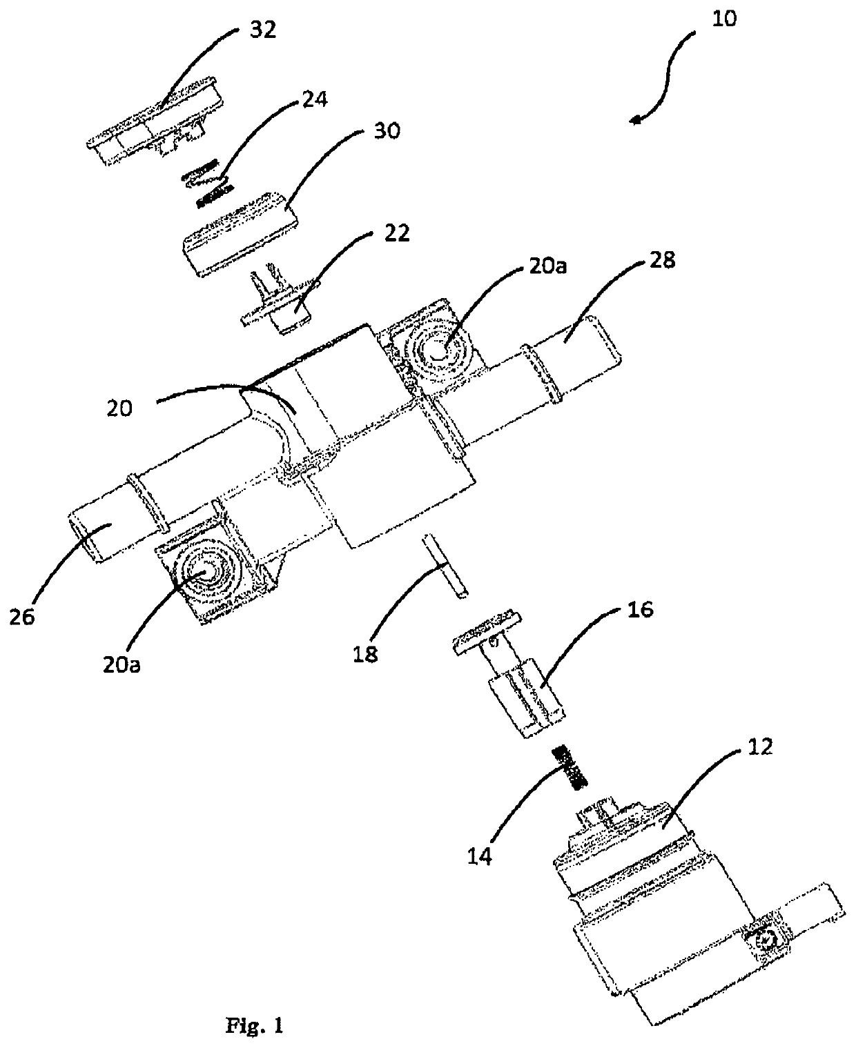
[0034]In one embodiment of present invention provides a fuel tank isolation valve (FTIV) w...


PUM


Abstract

A fuel tank isolation valve 10, wherein, the shaft 18 is assembled coaxially inside hole 42 of moving plunger 46 of seal sub assembly 16 and then flow limiter 22 is guided over the shaft 18 through guiding hole 34 to maintain sealing seat 36 in parallel with respect to the sealing surface 38 of rubber seal 44 and avoid misalignment of flow limiter 22 with respect to sealing surface 38 during and after the operation; the sealing seat 36 of flow limiter 22 on the sealing surface 38 of the rubber seal 44 fixed into moving plunger 46 of seal sub assembly 16 performs the over pressure relief function; the sealing surface 40 of rubber seal 44 fixed into moving plunger 46 of seal sub-assembly 16 is resting on surface 48 of nozzle body 20 to perform over vacuum relief function; and the rubber seal 44 assist both over pressure relief (OPR) and over vacuum relief (OVR) function.

Description

FIELD OF THE INVENTION[0001]The present invention relates to an improved fuel tank isolation valve. More specifically, the invention provides a system to incorporate over pressure relief (OPR) and over vacuum relief sealing (OVR) to eliminate the misalignment and customize sealing with lesser number of parts.BACKGROUND OF THE INVENTION[0002]Hybrid cars run most of the times with the electrical power and the combustion engine is idle. Since fuel tank is a closed system, thus in general due to evaporation of stored fuel it results in positive pressure inside the fuel tank. Moreover, it is necessary for vehicles to maintain an elevated pressure in the fuel tank to suppress the rate of fuel vapor generation and to minimize hydrocarbon emissions to the atmosphere. The most obvious solution, to overcome the problem is to provide a fuel tank isolation valve (FTIV) coupled to fuel tank to control fuel tank venting. The fuel tank isolation valve (FTIV) may be located in a conduit between a f...

Claims


Application Information

Patent Timeline
Patent Type & Authority Patents(United States)
IPC IPC(8): B60K15/035F16K17/196F02M25/08F16K31/06
CPCF16K31/0655B60K15/03519F02M25/0836F16K17/196B60K15/03504Y10T137/86324F02M2025/0845B60K2015/03296B60K2015/03302
Inventor BHANDARI, KABIRKUMAR, AMARDIPGERLICH, TORSTENKUMAR, VARUNSHARMA, KRISHAN KANTSINGLA, SAHIL
Owner PADMINI VNA MECHATRONICS PVT LTD
Why Eureka
Try Eureka