Eddy current heat generating apparatus
a heat generating apparatus and eddy current technology, applied in the direction of electric/magnetic/electromagnetic heating, asynchronous induction clutches/brakes, greenhouse gas reduction, etc., can solve the problems of carbon dioxide generation accompanying burning fossil fuels, and achieve the effect of sufficient heat generation, high magnetic flux density and thermal energy recovery
- Summary
- Abstract
- Description
- Claims
- Application Information
AI Technical Summary
Benefits of technology
Problems solved by technology
Method used
Image
Examples
first embodiment
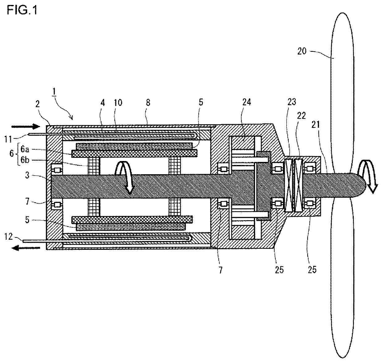
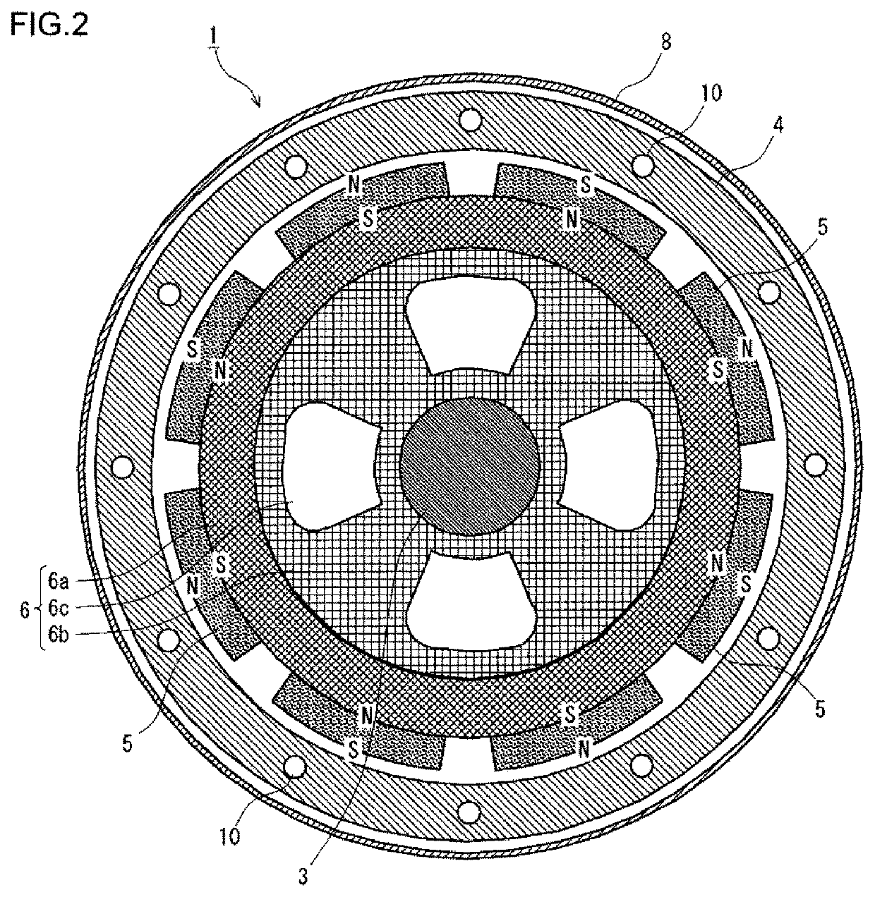
[0049]FIG. 1 is a longitudinal sectional view of a heat generating apparatus according to a first embodiment. FIG. 2 is a cross-sectional view of the heat generating apparatus according to the first embodiment. The heat generating apparatus illustrated in FIGS. 1 and 2 is mounted in a wind electric generating facility. The heat generating apparatus 1 according to the first embodiment includes a rotary shaft 3, a heat generator 4, a plurality of permanent magnets 5, and a magnet holder 6. The rotary shaft 3 is rotatably supported by a fixed non-rotative body 2 via a bearing 7.
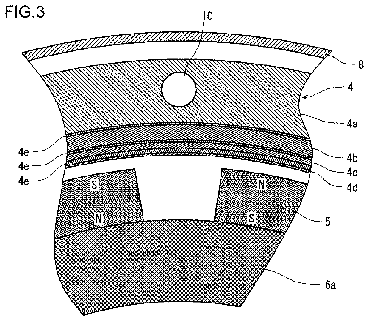
[0050]The heat generator 4 is a cylindrical member that is coaxial with the rotary shaft 3, and it is fixed to the body 2. The magnet holder 6 is disposed in the inner side of the heat generator 4, and it is fixed to the rotary shaft 3. The magnet holder 6 includes a cylindrical member 6a that is coaxial with the rotary shaft 3, and a disk-shaped connection member 6b connecting the cylindrical member 6a and the ...
second embodiment
[0068]FIG. 4 is a cross-sectional view of a heat generating apparatus 1 according to a second embodiment. The heat generating apparatus 1 according to the second embodiment is based on the structure of the heat generating apparatus 1 according to the first embodiment. The same applies to the third to sixth embodiments which will be described later. The heat generating apparatus 1 according to the second embodiment differs from the heat generating apparatus 1 according to the first embodiment principally in the way of arranging the magnets 5.
[0069]As shown in FIG. 4, the magnets 5 are circumferentially arrayed on the outer peripheral surface of the cylindrical member 6a across the whole circumference. The magnetic poles (north pole and south pole) of each of the magnets 5 are circumferentially arranged, and the magnetic pole arrangements of circumferentially adjacent ones of the magnets 5 are opposite to each other. In the second embodiment, the cylindrical member 6a directly holding...
third embodiment
[0072]FIG. 5 is a longitudinal sectional view of a heat generating apparatus according to a third embodiment. The heat generating apparatus 1 according to the third embodiment differs from the heat generating apparatus 1 according to the first embodiment principally in the way of arranging the magnets 5.
[0073]As shown in FIG. 5, the magnets 5 are axially arrayed on the outer peripheral surface of the cylindrical member 6a across the whole axial length. The magnets 5 are cylindrical. The magnetic poles (north pole and south pole) of each of the magnets 5 are axially arranged such that the magnetic pole arrangements of axially adjacent ones of the magnets 5 are opposite to each other. In the third embodiment, the cylindrical member 6a directly holding the magnets 5 is made of a non-magnetic material as with the second embodiment. Pole pieces 9 made of a ferromagnetic material are provided between the axially arrayed magnets 5. Further, pole pieces 9 are provided at both ends of the ax...
PUM
 Abstract
Description
Claims
Application Information
 - R&D
- Intellectual Property
- Life Sciences
- Materials
- Tech Scout
- Unparalleled Data Quality
- Higher Quality Content
- 60% Fewer Hallucinations
Browse by: Latest US Patents, China's latest patents, Technical Efficacy Thesaurus, Application Domain, Technology Topic, Popular Technical Reports.
© 2025 PatSnap. All rights reserved.Legal|Privacy policy|Modern Slavery Act Transparency Statement|Sitemap|About US| Contact US: help@patsnap.com


