Imaging lens

a technology of imaging lens and image, applied in the field of imaging lens, can solve the problems of difficult to form an image of the object on the imaging element, difficult to achieve a wider angle of view, difficult to satisfactorily correct aberrations, etc., and achieve satisfactory correction of aberrations, high resolution, and suitable for mounting

Active Publication Date: 2020-06-30
TOKYO VISIONARY OPTICS CO LTD
View PDF9 Cites 0 Cited by
  • Summary
  • Abstract
  • Description
  • Claims
  • Application Information

AI Technical Summary

Benefits of technology

[0020]Moreover, according to the imaging lens of the invention, the first lens group has negative refractive power, so that the arrangement of the refractive power is negative of the first lens group, positive of the third lens, and negative of the fourth lens in the order from the object side. With such negative-positive-negative arrangement, it is achievable to satisfactorily correct the chromatic aberration of magnification, the field curvature, the coma aberration, the astigmatism, and the distortion in a balanced manner. Here, when the first lens group has positive refractive power, it is advantageous for correction of the distortion. However, it is difficult to correct the axial chromatic aberration and the chromatic aberration of magnification. In addition, the outer coma aberration increases and the field curvature is insufficiently corrected. Therefore, it is difficult to obtain satisfactory image-forming performance.
[0032]According to the imaging lens of the invention, the second lens preferably has a positive refractive power. With the positive refractive power of the second lens, the positive refractive power of the whole lens system is shared between the two lenses, i.e., the second lens and the third lens. When the positive refractive power of the whole lens system is shared between two lenses, it is achievable to keep the refractive power of each lens weak than when the positive refractive power of the whole lens system is achieved by one lens. With this configuration, it is achievable to more satisfactorily correct the aberrations. Here, the positive refractive power of the second lens is preferably the weakest among those of the four lenses that compose the imaging lens.
[0033]According to the imaging lens having the above-described configuration, it is preferred to have a stop between the second lens and the third lens. Having the stop at a such position, it is achievable to satisfactorily correct the chromatic aberration and the astigmatism, while downsizing the imaging lens. In addition, it is also achievable to restrain an incident angle of a light beam emitted from the imaging lens to an image plane of the imaging element within the range of a chief ray angle (CRA).
[0040]When the imaging lens of the invention has an angle of view 2ω, the imaging lens preferably satisfies 100°≤2ω. When the imaging lens satisfies this conditional expression, the imaging lens can have a wider angle of view, and it is suitably achievable to attain both downsizing and a wider angle of view of the imaging lens.
[0042]According to the imaging lens of the invention, it is achievable to provide an imaging lens having a wide angle of view, which is especially suitable for mounting in a small-sized camera, while having high resolution with satisfactory correction of aberrations.

Problems solved by technology

However, it is difficult to attain a wider angle of view, as well as satisfying the requirements of smaller size and higher resolution, while satisfactorily correcting aberrations.
For example, when downsizing of an imaging lens is attempted, refractive power of each lens tends to be strong, so that it is difficult to satisfactorily correct aberrations.
For this reason, in a case of general wide-angle lenses, a focal position of near-infrared light significantly changes relative to that of visible light in the dark and it is difficult to form an image of the object on an imaging element.
However, in case of conventional imaging lens having wide angles, such as the one described in Patent Reference, it is difficult to achieve satisfactorily image-forming performance over wide wavelength range from that of visible light to that of near-infrared light.
Here, such problem is not unique to the imaging lens for mounting in an onboard camera.
The above-described problems are common among imaging lenses for mounting in relatively small-sized cameras.

Method used


Image

  • Imaging lens
  • Imaging lens
  • Imaging lens

Examples


Embodiment Construction

[0064]Hereunder, referring to the accompanying drawings, an embodiment of the present invention will be fully described.

[0065]Hereunder, referring to the accompanying drawings, an embodiment of the present invention will be fully described.

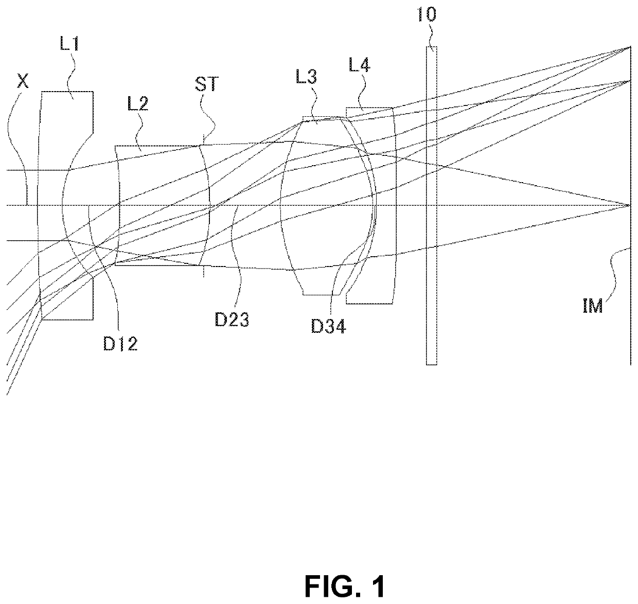
[0066]FIGS. 1, 4, 7, 10, 13, 16, and 19 are schematic sectional views of the imaging lenses in Numerical Data Examples 1 to 7 according to the embodiment, respectively. Since the imaging lenses in those Numerical Data Examples have the same basic configuration, the lens configuration of the embodiment will be described with reference to the illustrative sectional view of Numerical Data Example 1.

[0067]According to the embodiment of the invention, the imaging lens includes a first lens group having negative refractive power, an aperture stop, and a second lens group. The first lens group is composed of a first lens and a second lens. The second lens group is composed of a third lens and a fourth lens. When a composite focal length of the first lens...


PUM


Abstract

An imaging lens includes a first lens group; and a second lens group, arranged from an object side to an image plane side. The first lens group includes a first lens having negative refractive power and a second lens. The second lens group includes a third lens having positive refractive power and a fourth lens having negative refractive power. The fourth lens is formed in a shape so that a curvature radius of a surface thereof on the image plane side is positive. The first lens, the second lens and the third lens have specific Abbe's numbers, the first lens is arranged to be away from the second lens, the second lens is arranged to be away from the third lens, and the third lens is arranged to be away from the fourth lens by specific distances on an optical axis so that the specific conditional expressions are satisfied.

Description

BACKGROUND OF THE INVENTION AND RELATED ART STATEMENT[0001]The present invention relates to an imaging lens for forming an image of an object on an imaging element such as a CCD sensor and a CMOS sensor. In particular, the present invention relates to an imaging lens suitable for mounting in a relatively small camera such as a smartphone and a cellular phone, a digital camera, an infrared camera, a digital video camera, an onboard camera, a network camera, a TV conference camera, a fiberscope, and a capsule endoscope.[0002]In these years, some vehicles are equipped with a plurality of cameras for improving convenience and / or security. For example, in case of a vehicle equipped with a backup camera, a driver can see the view behind the vehicle on a display upon backing up. Therefore, the driver can safely move the car backward without hitting any objects including the ones invisible by the driver from inside. Such camera for mounting in a vehicle, so-called “onboard camera”, is expec...

Claims


Application Information

Patent Timeline
Patent Type & Authority Patents(United States)
IPC IPC(8): G02B9/58G02B13/00G02B27/00
CPCG02B13/004G02B9/58G02B27/0025G02B13/06G02B13/18
Inventor KUBOTA, YOJIKUBOTA, KENICHIHIRANO, HITOSHIFUKAYA, HISAO
Owner TOKYO VISIONARY OPTICS CO LTD
Why Eureka
Try Eureka