Reduced iron manufacturing method
a manufacturing method and technology of reduced iron, applied in the direction of electric furnaces, furnace types, furnaces, etc., can solve the problems of increased production equipment costs, difficult preparation of agglomerates before heating, etc., and achieve the effect of improving the yield of reduced iron
Active Publication Date: 2020-06-16
KOBE STEEL LTD
View PDF22 Cites 0 Cited by
- Summary
- Abstract
- Description
- Claims
- Application Information
AI Technical Summary
Benefits of technology
This approach increases the yield of reduced iron and improves its aggregation, leading to higher productivity and reduced costs by optimizing the ratio of carbonaceous reducing agents and iron oxide oxygen content, resulting in a more efficient and cost-effective manufacturing process.
Problems solved by technology
However, when a carbonaceous reducing agent having a particle diameter of 400 μm or more is used, it may be difficult to prepare an agglomerate before heating.
This leads to a disadvantage of increase in the costs of the production equipment.
Method used
View moreImage
Smart ImageViewing Examples


Examples
examples
[0073]Hereafter, the present invention will be described in more detail by way of Examples, but the present invention is not limited by these Examples.
Login to View More PUM
| Property | Measurement | Unit |
|---|---|---|
| particle diameter | aaaaa | aaaaa |
| particle diameter | aaaaa | aaaaa |
| particle diameter | aaaaa | aaaaa |
Abstract
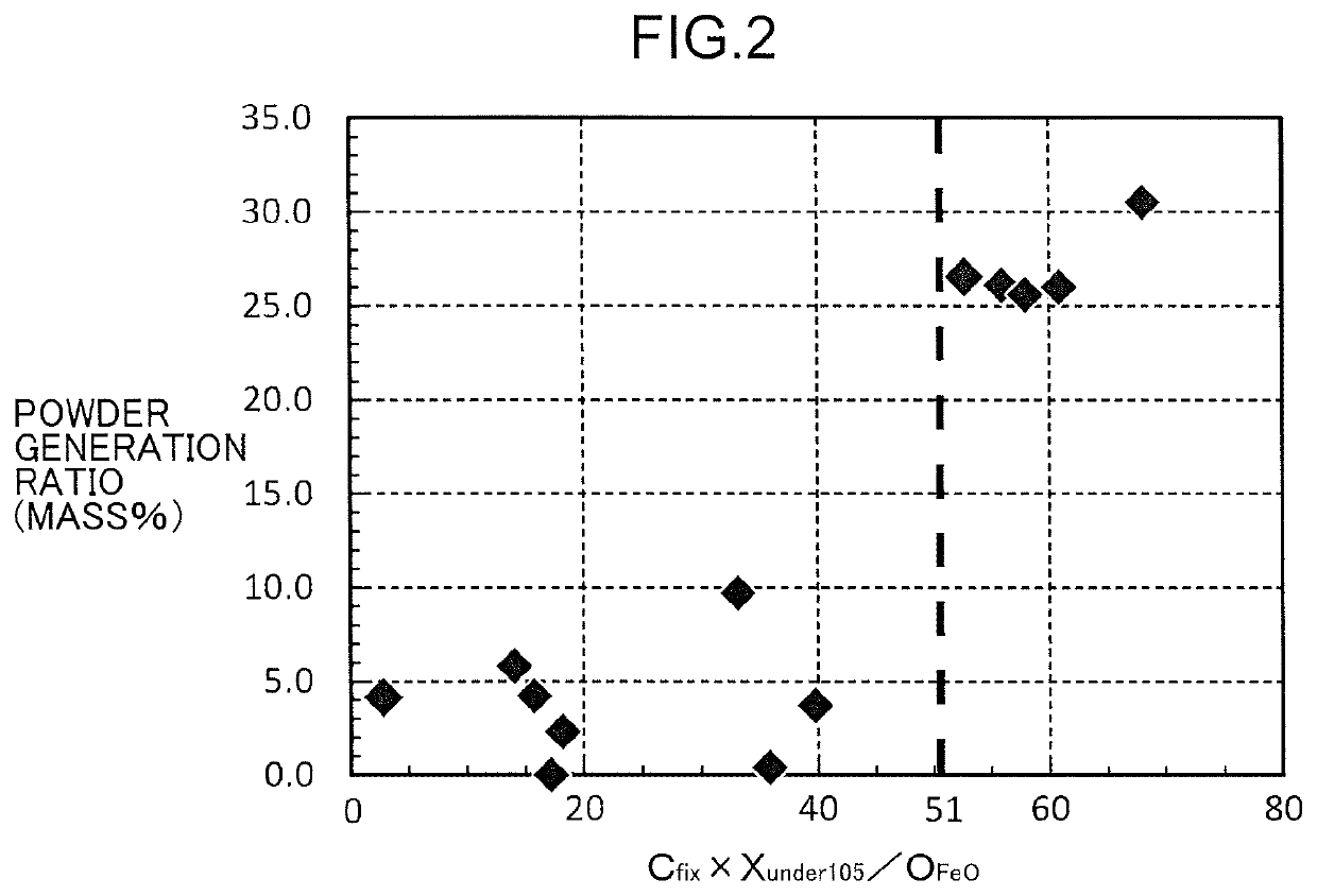
The reduced iron manufacturing method of the present invention includes preparing an agglomerate by agglomerating a mixture containing an iron oxide-containing substance and a carbonaceous reducing agent, and preparing reduced iron by heating the agglomerate to reduce iron oxide in the agglomerate, characterized in that Expression (I) as follows is satisfied:Cfix×Xunder105 / OFeO≤51 (I)where OFeO is the mass percentage of oxygen contained in the iron oxide in the agglomerate, Cfix is the mass percentage of total fixed carbon contained in the agglomerate, and Xunder105 is the mass percentage of particles having a particle diameter of 105 μm or less with respect to the total mass of particles configuring the carbonaceous reducing agent.
Description
TECHNICAL FIELD[0001]The present invention relates to a method for manufacturing reduced iron by heating an agglomerate containing an iron oxide source such as iron ore (which may hereafter be referred to as “iron oxide-containing substance”) and a carbonaceous reducing agent containing carbon such as coal, so as to reduce iron oxide in the agglomerate.BACKGROUND ART[0002]The direct reduction iron-making method is developed as a method for manufacturing reduced iron by reducing iron oxide contained in an iron oxide-containing substance.[0003]For industrial implementation of the above direct reduction iron-making method, there are a lot of issues that must be addressed, such as improvement in operation stability, economical efficiency, and reduced iron quality. The techniques of Patent Literatures 1 to 9 are proposed as an attempt to address such issues.[0004]Among the above issues, improvement in the yield of reduced iron is particularly considered important in recent years. This is...
Claims
Login to View More Application Information
Patent Timeline
 Patent Type & Authority Patents(United States)
IPC IPC(8): C22B1/24C22B1/245C21B13/00
CPCC21B13/00C22B1/245C22B1/24C21B13/12C21B13/0053C21B13/006C21B13/0066C21B13/105
Inventor HOSONO, YUISHIMAMOTO, MASAKIHARADA, TAKAOYOSHIDA, SHINGOKIKUCHI, SHOICHIHATAKEYAMA, TAIJI
Owner KOBE STEEL LTD
Features
- R&D
- Intellectual Property
- Life Sciences
- Materials
- Tech Scout
- Unparalleled Data Quality
- Higher Quality Content
- 60% Fewer Hallucinations
Learn More Browse by: Latest US Patents, China's latest patents, Technical Efficacy Thesaurus, Application Domain, Technology Topic, Popular Technical Reports.
© 2025 PatSnap. All rights reserved.Legal|Privacy policy|Modern Slavery Act Transparency Statement|Sitemap|About US| Contact US: help@patsnap.com