
Actuator, in particular, for a motor vehicle

a motor vehicle and actuator technology, applied in the direction of mechanical control devices, limiting/preventing/returning movement of parts, manual control with single control member, etc., can solve the problem of cumbersome design of the detection of adjustment positions, and achieve the effect of significantly simplifying the overall system, saving costs, and facilitating the user

Active Publication Date: 2020-06-09
MARQUARDT GMBH SCHLOSSTRASSE 16 7201 RIETHEIM-WEILHEIM 1 WEST GERMANY
View PDF27 Cites 0 Cited by
  • Summary
  • Abstract
  • Description
  • Claims
  • Application Information

AI Technical Summary

Benefits of technology

The present invention aims to improve the control element by simplifying the detection of adjustment positions. It does this by using a code carrier with a unique coding for the adjustment positions, which is sensed by a sensor. This results in a high level of functional reliability for detecting all adjustment positions. The control element is designed to be more cost-effective and robust.

Problems solved by technology

The means for the detection of the adjustment positions is of cumbersome design in the case of the known control element.

Method used


Image

  • Actuator, in particular, for a motor vehicle
  • Actuator, in particular, for a motor vehicle
  • Actuator, in particular, for a motor vehicle

Examples


Embodiment Construction

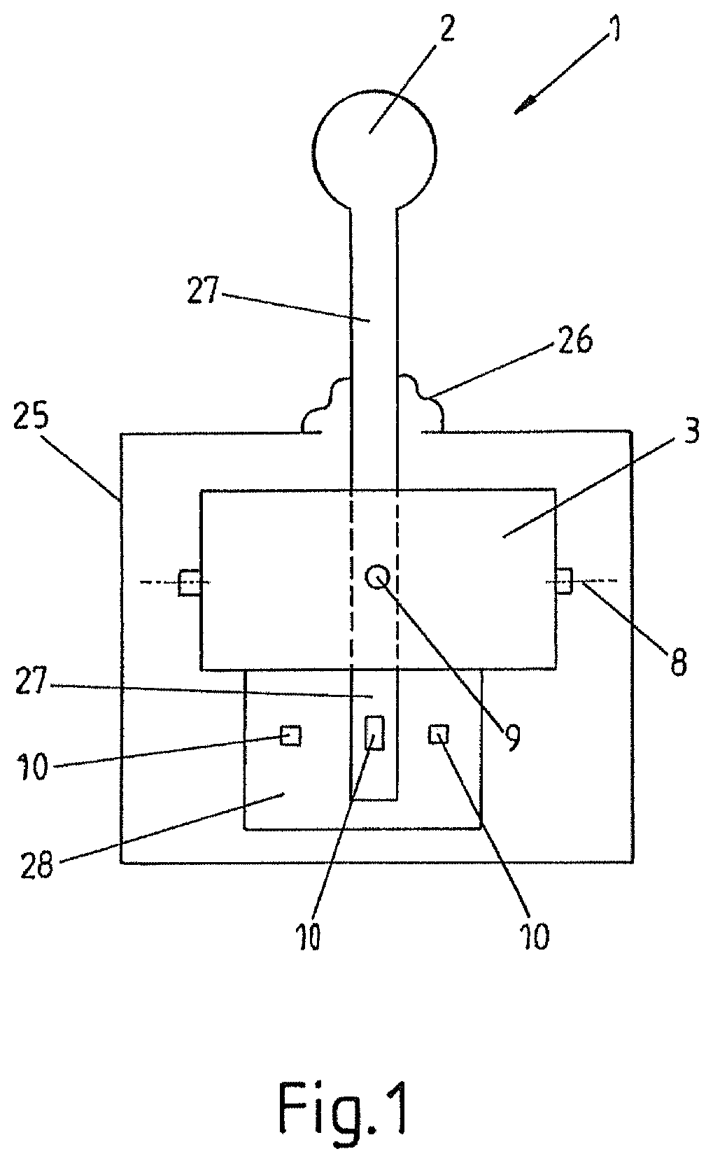
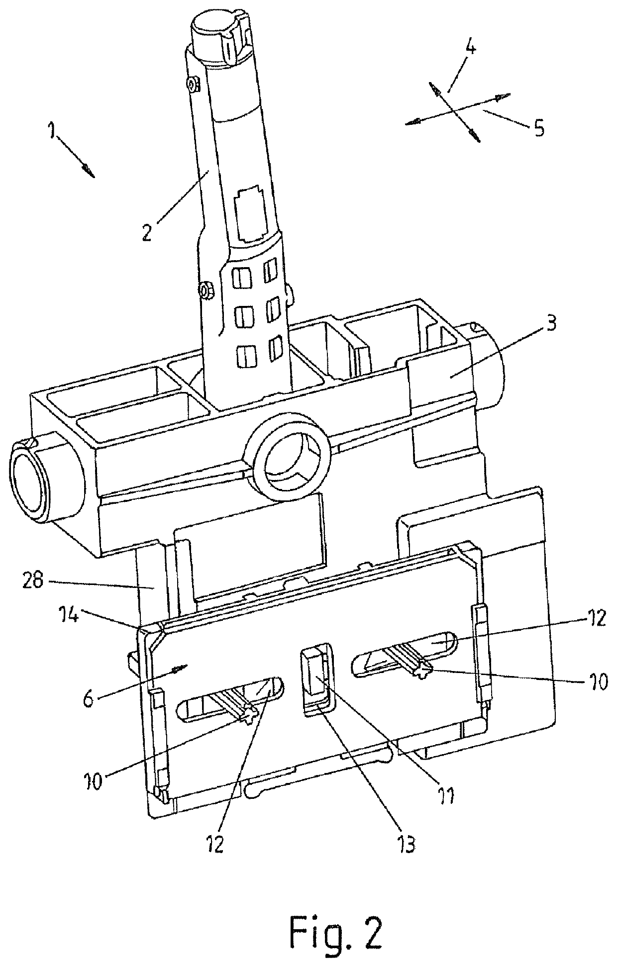
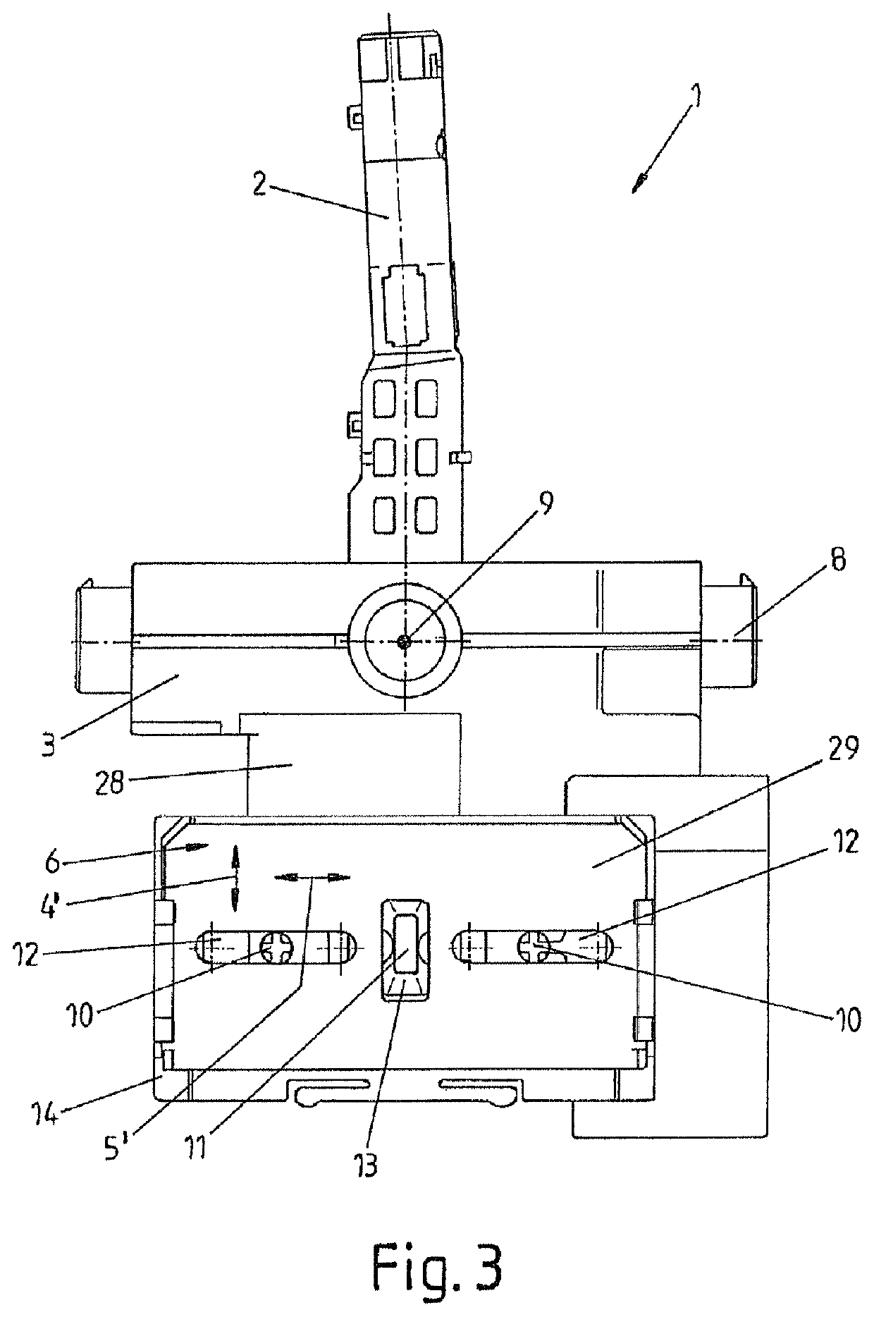
[0051]FIG. 1 shows a control element 1 which serves for the manual actuation of functions in a motor vehicle and which is used, in particular, as a gear selector switch for a shift-by-wire gearshift device. The control element 1 is equipped with a movable handle 2 in the form of a selector lever, wherein the handle 2 projects out of a housing 25 of the control element 1 in a manner sealed by way of a movable sleeve 26. The handle 2 is mounted movably on a carrier 3 which is situated in the housing 25, in such a way that the handle 2 is adjustable in at least one direction, preferably in two different directions 4, 5 (see FIG. 2) from a neutral position into at least in each case one adjustment position associated with the respective direction 4, 5. In this way, the handle 2 can be adjusted manually by the user into the adjustment positions, whereby the respectively desired functions in the motor vehicle are triggered, for example, by way of correspondingly generated signals.

[0052]Th...


PUM


Abstract

A control element, in particular, a switching device for the manual actuation of functions in a motor vehicle, having a handle. The handle is mounted on a carrier such that the handle is adjustable in two different directions from a neutral position into adjustment positions. The control element furthermore can detect the adjustment positions, with the control element having a code carrier for the detection of the adjustment positions, which encodes the adjustment positions, and a sensor which senses the coding, in such a way that all adjustment positions can be detected by way of the one code carrier.

Description

CROSS REFERENCE TO RELATED APPLICATIONS[0001]This application is a continuation of International Application No. PCT / EP2014 / 075818 filed Nov. 27, 2014, which designated the United States, and claims the benefit under 35 USC § 119(a)-(d) of German Application Nos. 10 2013 017 969.6, 10 2013 017 968.8 and 10 2013 017 966.1, each filed Nov. 29, 2013, the entireties of which are incorporated herein by reference.FIELD OF THE INVENTION[0002]The present invention relates to a control element.BACKGROUND OF THE INVENTION[0003]Control elements, such as electrical and / or electronics switching devices in the form of a joystick and / or cursor switch, serve for the manual actuation of functions in a motor vehicle. Inter alia, such switching devices are used for the inputting of data for an electrical unit by a user, for example, in the case of automobile radios, navigation units, on-board computers or similar units in the motor vehicle. In particular, a control element of this type may also be use...

Claims


Application Information

Patent Timeline
Patent Type & Authority Patents(United States)
IPC IPC(8): G05G9/047G05G5/00F16H59/02F16H59/10
CPCG05G5/005G05G9/047F16H59/105G05G2009/0474H03K2217/96062F16H2059/0273G05G2009/04751F16H59/02F16H2306/00
Inventor BUSCHLE, ROLANDBERCHTOLD, RAINERMASA, ROBERT
Owner MARQUARDT GMBH SCHLOSSTRASSE 16 7201 RIETHEIM-WEILHEIM 1 WEST GERMANY
Learn More