
Unified and redundant flight and mission control for an unmanned aerial vehicle

a technology for unmanned aerial vehicles and flight and mission control, applied in process and machine control, energy-efficient board measures, instruments, etc., can solve the problems of increasing the frequency of needed docking and maintenance, and consuming more power of uavs. , to achieve the effect of reducing the cost of operation, reducing the size, weight and power (swap) specifications

Active Publication Date: 2020-05-26
META PLATFORMS INC
View PDF3 Cites 0 Cited by
  • Summary
  • Abstract
  • Description
  • Claims
  • Application Information

AI Technical Summary

Benefits of technology

The patent text describes a system that combines flight control, mission processing, and data concentrator functionality in a single device. This reduces the size, weight, and power requirements of UAVs, resulting in cost savings during development, production, and servicing. The system also includes features that decrease the space needed for the UAV while ensuring reliability. Overall, the patent describes a technology that makes UAVs lighter, more efficient, and more reliable.

Problems solved by technology

While increased usage of UAVs have reduced the cost and increased the ease of various flight operations, UAVs have various difficulties and drawbacks.
In addition, with increased functionality and more complex missions, UAVs often require electrical housing, circuitry, power supplies, and other electrical components that contribute to the overall weight of the UAV.
Increased and more complicated payloads cause UAVs to consume more power and increase the frequency of needed docking and maintenance.
These redundancies, when implemented as single function and separate Line Replaceable Units (LRU), contribute substantially to the overall weight of the UAV and cause the UAV to consume more power.
In addition, having redundant LRUs contributes to the costs of developing, producing, servicing, and operating the UAV.
These and other problems exist with regard to UAVs.

Method used


Image

  • Unified and redundant flight and mission control for an unmanned aerial vehicle
  • Unified and redundant flight and mission control for an unmanned aerial vehicle
  • Unified and redundant flight and mission control for an unmanned aerial vehicle

Examples


Embodiment Construction

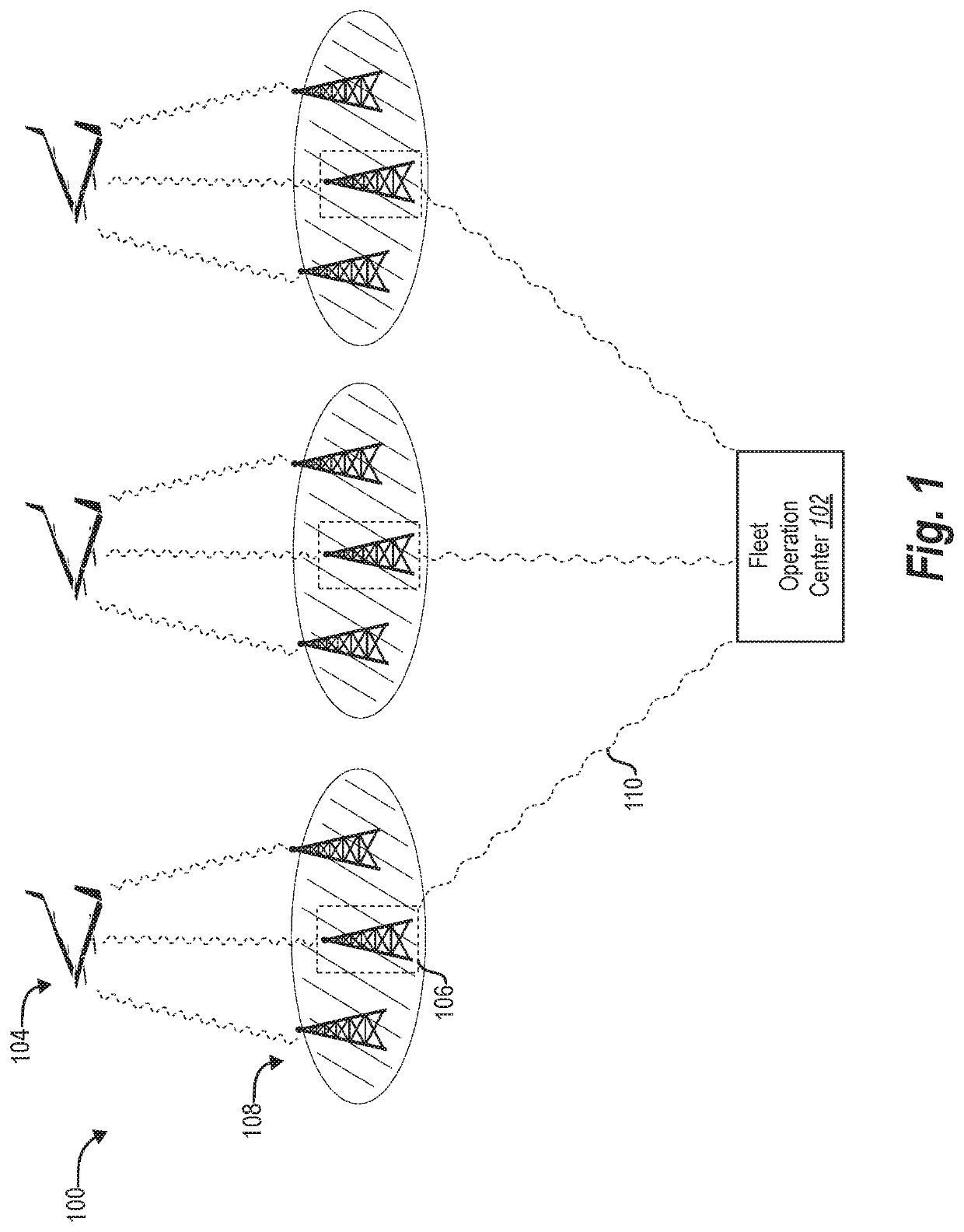
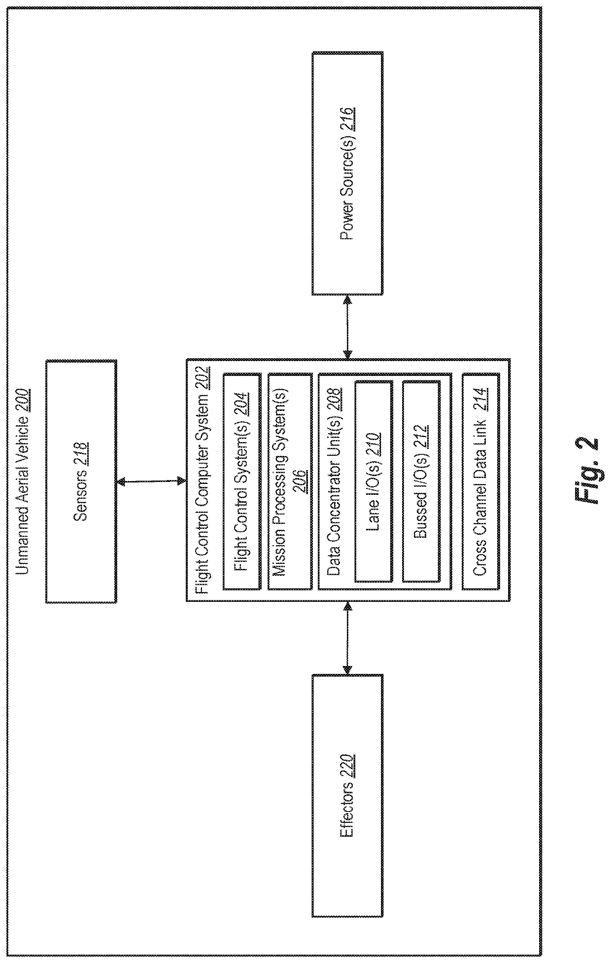
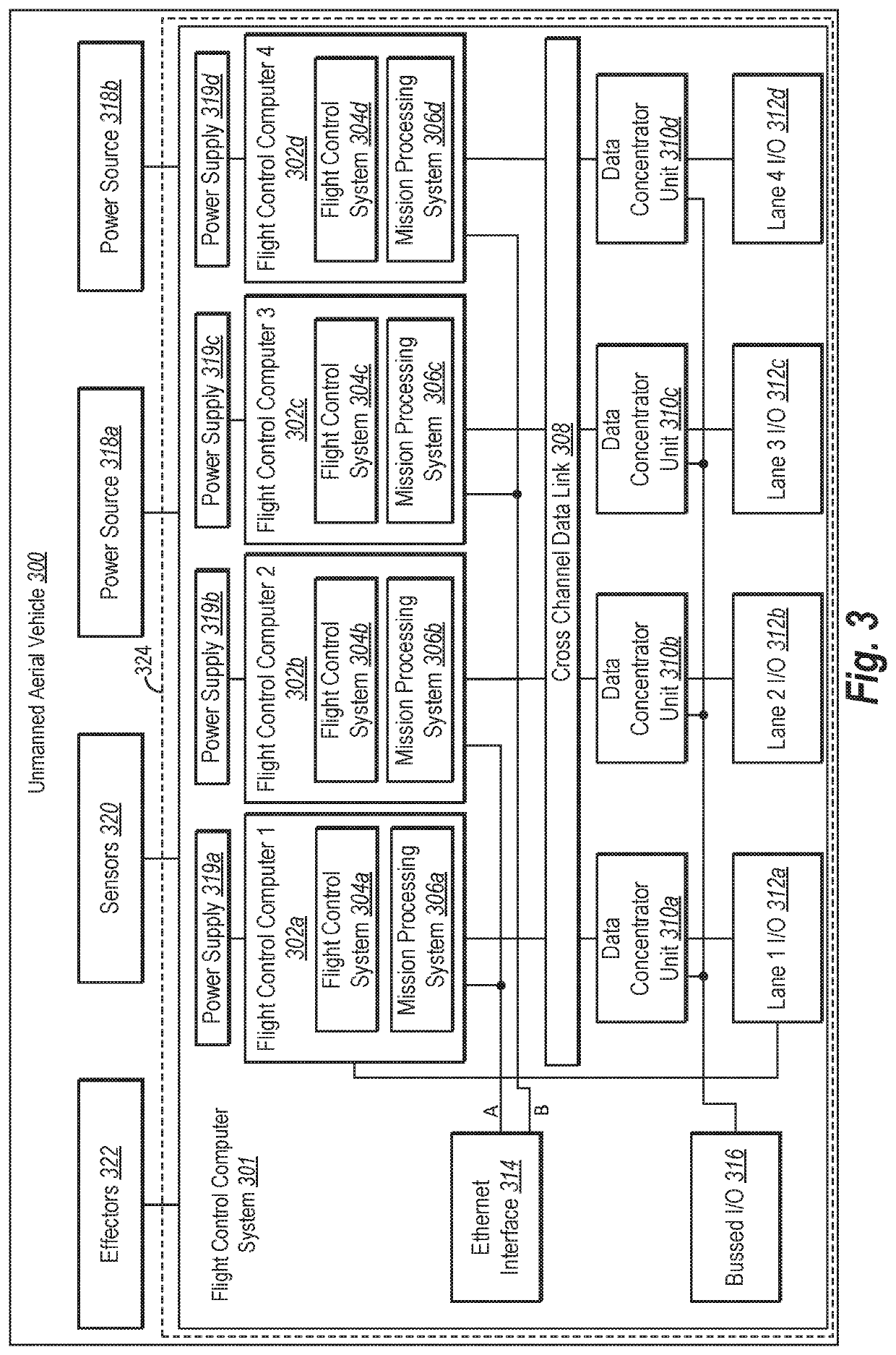
[0013]One or more embodiments described herein relate to a flight control computer (FCC) system that includes features and functionality that reduce the size, weight, and power (SWaP) for an unmanned aerial vehicle (UAV) while maintaining reliable functionality of both flight control and mission processing for the UAV. For example, in one or more embodiments, the FCC system incorporates combined hardware that provides both flight control functionality (e.g., flight critical functionality) in addition to mission processing functionality of the UAV. In particular, the FCC system includes multiple processing lanes that each include hardware for executing both flight control functionality and mission processing functionality.

[0014]In particular, one or more embodiments described herein relate to a flight control computer (FCC) that includes a plurality of processing lanes for executing flight control functions and mission processing functions. For example, each processing lane includes ...


PUM


Abstract

One or more embodiments of the present disclosure include features and functionality that reduce size, weight, and power (SWaP) specifications for an unmanned aerial vehicle (UAV) by combining flight control functionality with mission processing functionality within common hardware. By implementing flight control and mission processing functionality using common hardware, systems and methods described herein decrease costs associated with developing, producing, servicing, and operating UAVs. Moreover, the systems and methods described herein include features that reduce the SWaP for the UAV while providing further redundancies that maintain reliability of the UAV.

Description

CROSS REFERENCE TO RELATED APPLICATIONS[0001]This application claims the benefit of and priority to U.S. Provisional Patent Application No. 62 / 541,548, filed Aug. 4, 2017, which is incorporated herein by reference in its entirety.BACKGROUND[0002]Aerial vehicles are becoming increasingly common. For example, consumers, governments, and various enterprises have begun to utilize unmanned aerial vehicles (UAVs) to perform various operations. While increased usage of UAVs have reduced the cost and increased the ease of various flight operations, UAVs have various difficulties and drawbacks. For example, UAVs generally need to periodically refuel, recharge, and / or receive maintenance in order to operate reliably. In addition, with increased functionality and more complex missions, UAVs often require electrical housing, circuitry, power supplies, and other electrical components that contribute to the overall weight of the UAV. Increased and more complicated payloads cause UAVs to consume m...

Claims


Application Information

Patent Timeline
Patent Type & Authority Patents(United States)
IPC IPC(8): G05D1/00G05D1/10B64C39/02
CPCG05D1/104B64C39/024G05D1/0022G05D1/0077G05D1/0027B64C2201/066B64C2201/028B64C2201/042B64C2201/146B64D2211/00Y02T50/50B64U2201/10B64U2201/20B64U50/31B64D27/353
Inventor ORTIZ, JOSE ENRIQUEROODSELAAR, ARJEN
Owner META PLATFORMS INC
Learn More