Brush seal assembly

a technology of brush seals and assembly parts, which is applied in the direction of engine seals, leakage prevention, machines/engines, etc., can solve the problems of power loss, degrade energy efficiency, and limit the narrowing gap, so as to improve the sealing safety of rotating bodies and improve stability. operation

Active Publication Date: 2020-05-26
DOOSAN HEAVY IND & CONSTR CO LTD
View PDF24 Cites 0 Cited by
  • Summary
  • Abstract
  • Description
  • Claims
  • Application Information

AI Technical Summary

Benefits of technology

[0009]An object of the present invention is to improve a stable operation and an output of a gas turbine by improving sealing safety of a rotating body and a brush seal assembly surrounding the rotating body.
[0010]An object of the present invention is to improve sealing safety of a brush seal assembly surrounding a rotor of a gas turbine and minimize problems due to a deformation and a stress concentration of components configuring the brush seal assembly.

Problems solved by technology

Therefore, due to a gap existing between the fixed body and the rotating body, the high-pressure fluid tends to leak through the gap, which would cause a power loss and thus degrade energy efficiency.
However, as a practical matter, there are limitations in narrowing the gap.
For example, if the gap is excessively narrow, the rotating body and the fixed body may interfere with each other when the rotating body is shaft-rotated.
The interference, or rubbing, generates vibrations which can seriously damage the turbine.
The potential for interference exists under normal conditions of being operated, including starting and stopping, whereby a steam turbine expands and contracts from several millimeters to several tens of millimeters depending on the point of measurement, because high-temperature steam introduced from a boiler applies heat throughout the rotating body and the fixed body.

Method used


Image

  • Brush seal assembly
  • Brush seal assembly
  • Brush seal assembly

Examples


Embodiment Construction

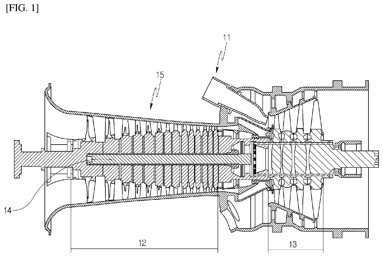
[0047]A description will be given of a basic configuration of a gas turbine in which a brush seal assembly is installed, before a description of the brush seal assembly according to an embodiment of the present invention. That is, main components of the gas turbine provided with the brush seal assembly according to the present embodiment will first be described with reference to FIG. 1.

[0048]The gas turbine is provided with a casing 15 which forms an outer appearance. A rear side of the casing 15 is provided with a diffuser to which combustion gas passing through the turbine is discharged. A front side of the diffuser is provided with a combustor 11, which introduces compressed air to a front side of the turbine and combusts the compressed air.

[0049]In terms of airflow direction, a compressor section 12 is located upstream of the casing 15, and a turbine section 13 is located downstream thereof.

[0050]A torque tube 14 is provided as a torque transmission member, between the compresso...


PUM

PropertyMeasurementUnit
stress concentrationaaaaaaaaaa
diameteraaaaaaaaaa
lengthaaaaaaaaaa

Abstract

A brush seal assembly includes a brush seal, a brush support portion, and an assembly support portion. The brush seal, which has a multitude of bristles forming an angle with respect to a radial direction of a rotating body rotated inside a casing, is disposed around an outer circumferential surface of the rotating body and is oriented with respect to the body's rotating direction. The brush support portion supports the brush seal by extending toward the rotating body while contacting a low-pressure side of the brush seal. The assembly support portion supports the brush seal and the brush support portion and to receive respectively a base end of the brush seal and an axial protrusion of the brush support portion. The brush support portion contacts the brush seal along a predetermined length, which is greater than that of a line following a bristle of the brush seal.

Description

CROSS-REFERENCE TO RELATED APPLICATION[0001]This application claims priority to Korean Patent Application No. 10-2017-0078146, filed on Jun. 20, 2017, the disclosure of which is incorporated herein by reference in its entirety.BACKGROUND OF THE INVENTIONField of the Invention[0002]Exemplary embodiments of the present invention relate to a brush seal assembly, and more particularly, to a brush seal assembly for preventing a deformation of a brush seal caused by friction and stress forces applied to the brush seal.Description of the Related Art[0003]Generally, a turbine is a power generation apparatus which converts heat energy of fluids such as gas or steam into a torque, which is mechanical energy, and includes a rotor and a casing. The rotor may be provided with a plurality of buckets to be shaft-rotated by the fluid, and the casing is installed around the rotor's circumference and may be provided with a plurality of diaphragms.[0004]Among turbines, a gas turbine is configured to i...

Claims


Application Information

Patent Timeline
Patent Type & Authority Patents(United States)
IPC IPC(8): F16J15/3288F16J15/3292F01D11/00F01D11/02
CPCF16J15/3292F16J15/3288F05D2240/57F01D11/001F05D2220/32F05D2220/31F05D2240/56F05D2240/59F01D11/02
Inventor AKSIT, MAHMUT FARUK
Owner DOOSAN HEAVY IND & CONSTR CO LTD
Why Eureka
Try Eureka