
Magnetic elements for processing fluids

a technology of magnetic elements and processing fluids, applied in the field of magnetic elements for processing fluids, can solve the problems of long mixing time, strong reaction limitation, and ineffective micro-scale, and achieve the effect of rapid and efficient mixing of fluids and/or capturing target analytes

Active Publication Date: 2020-05-19
DH TECH DEVMENT PTE
View PDF13 Cites 3 Cited by
  • Summary
  • Abstract
  • Description
  • Claims
  • Application Information

AI Technical Summary

Benefits of technology

The present patent teaches how to use magnetic elements to process fluids on a small or large scale. By arranging the magnetic elements with the fluid, they can be influenced by a magnetic field to move and mix the fluid effectively. This can help capture target analytes within the fluid. Overall, this technology allows for efficient and effective mixing and analysis of fluids.

Problems solved by technology

However, conventional mass transfer within a microfluid droplet is a function of molecular diffusion, resulting in long mixing times. Indeed, as for any surface-based assay, the reaction is strongly limited by the natural diffusion process.
However, these have not proven effective at the micro-scale, particularly for DMF devices.
However, with this method the magnetic field gradient may attract and confine the particles in a cavity region close to the walls of the container.
In such a condition, the contact between the particles and the test medium is limited to the cavity space, which greatly reduces mixing efficiency.
As such, the magnetic particles would not be capable of facilitating sample mixing or separation because their movement and exposure to the sample volume becomes highly limited.

Method used


Image

  • Magnetic elements for processing fluids
  • Magnetic elements for processing fluids
  • Magnetic elements for processing fluids

Examples


Embodiment Construction

[0029]Those skilled in the art will understand that the methods, systems, and apparatus described herein are non-limiting exemplary embodiments and that the scope of the applicant's disclosure is defined solely by the claims. While the applicant's teachings are described in conjunction with various embodiments, it is not intended that the applicants' teachings be limited to such embodiments. On the contrary, the applicant's teachings encompass various alternatives, modifications, and equivalents, as will be appreciated by those of skill in the art. The features illustrated or described in connection with one exemplary embodiment may be combined with the features of other embodiments. Such modifications and variations are intended to be included within the scope of the applicants' disclosure. Various terms are used herein consistent with their customary meanings in the art. The term “about” as used herein indicates a variation of less than 10%, or less than 5%, or less than 2%.

[0030]...


PUM

PropertyMeasurementUnit
volumesaaaaaaaaaa
lengthaaaaaaaaaa
diameteraaaaaaaaaa

Abstract

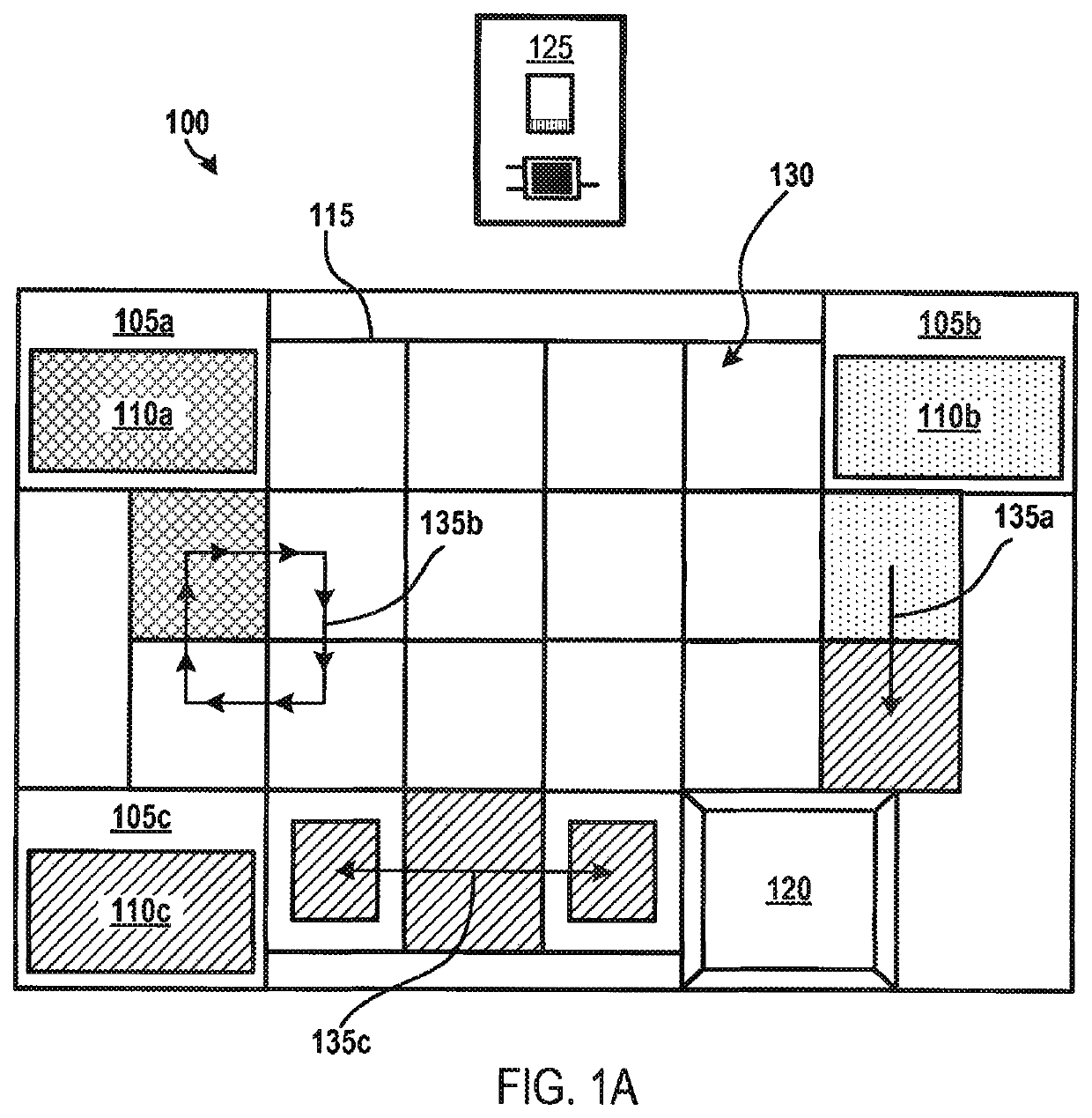
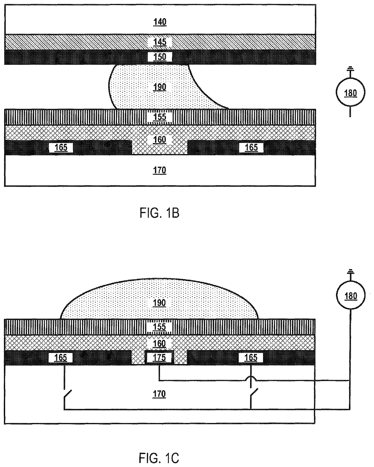
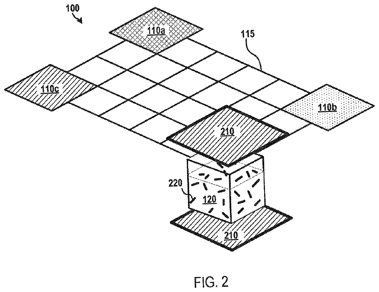
Methods and apparatus for processing fluids on a macro- or micro-scale are described. In various aspects, a fluid may have a plurality of elongated (i.e., substantially rod-shaped) magnetic elements disposed therein within a fluid container. An illustrative fluid container is an actuator electrode or a processing vial of a microfluidic device, such as a digital microfluidic device. A magnet component may be configured to generate a magnetic force sufficient to influence the movement of the plurality of elongated magnetic elements within the fluid to be processed. For example, the magnetic force (or magnetic force gradient) may influence the plurality of elongated magnetic elements to rotate, spin, and / or move laterally side-to-side. The shape and movements of the plurality of elongated magnetic elements facilitate the rapid and efficient processing of the fluid, such as fluid mixing and / or fluid separation.

Description

RELATED APPLICATION[0001]This application claims priority to U.S. provisional application No. 61 / 946,364, filed on Feb. 28, 2014, which is incorporated herein by reference in its entirety.FIELD[0002]The present teachings generally relate to processing fluids and, more particularly, to methods and apparatus for processing fluids on a micro- or macro-scale using magnetic elements (e.g., elongated magnetic elements).INTRODUCTION[0003]The use of fluids on a micro- and macro-scale has facilitated advancements in many technological fields, including ink jet printing, medical implants, sample preparation for mass spectrometers and gas chromatographs, industrial process control equipment, and lab-on--chip applications, in which biological assays and chemical analysis are performed on a microchip-sized wafer of glass, plastic, or silicon. In general, macro-scale fluid processing involves working with volumes in the milliliter range, while micro-scale fluid processing involves working with vo...

Claims


Application Information

Patent Timeline
Patent Type & Authority Patents(United States)
IPC IPC(8): G01N33/553B01L3/00G01N35/00B01F13/08B01F13/00G01N33/543G01N1/38G01N27/74
CPCB01F13/0818G01N33/54326B01L3/502792G01N1/38B01L3/50273B01F13/0059G01N35/0098G01N27/745B01L2400/043G01N2001/386B01L2400/0427B01L2200/0647B01L2300/0819B01F33/30B01F33/452
Inventor CAMPBELL, JOHN L.COVEY, THOMAS R.LIU, CHANGPURKAYASTHA, SUBHASISH
Owner DH TECH DEVMENT PTE
Learn More