
Tooth modeling system

a technology of tooth modeling and model, applied in the direction of impression caps, image enhancement, instruments, etc., can solve the problems of root resorption, complex treatment of braces, and inability to shorten treatment tim

Active Publication Date: 2020-04-21
ULAB SYST INC
View PDF455 Cites 17 Cited by
  • Summary
  • Abstract
  • Description
  • Claims
  • Application Information

AI Technical Summary

Benefits of technology

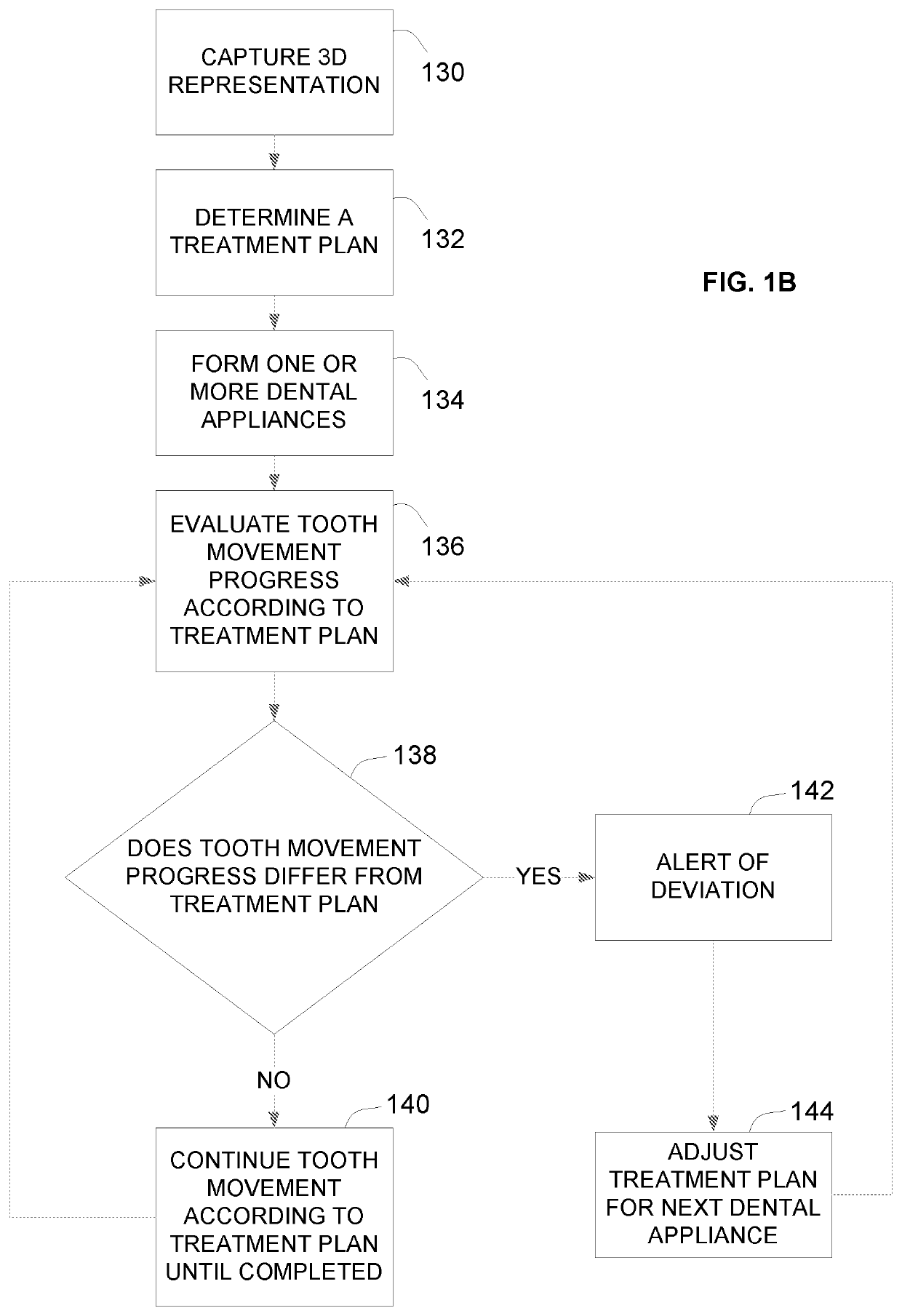
The patent describes a system that allows a dental professional to control the movement of tooth models in a way that is safe and synchronized. This system makes it possible to have a few tooth models move in a choreographed manner dictated by a dentist, rather than have them move randomly and independently. The system also avoids collisions between the teeth and ensures that the tooth models react safely to changes in bone structure and soft tissue during group tooth movement. Overall, this system allows for more precise and safe dental treatments.

Problems solved by technology

Treatment with braces is complicated by the fact that it is uncomfortable and / or painful for patients, and the orthodontic appliances are perceived as unaesthetic, all of which creates considerable resistance to use.
Further, the treatment time cannot be shortened by increasing the force, because too high a force results in root resorption, as well as being more painful.
However, this idea did not become practical until the advent of three-dimensional (3D) scanning and use of computers by companies including Align Technologies and as well as OrthoClear, ClearAligner, and ClearCorrect to provide greatly improved aesthetics since the devices are transparent.
However for traditional trim model to individual tooth, the gum geometry is lost and the fake gum is recreated, often remodeled by a technician.
Hence, the gum geometry may not be accurate at first and an animation of gum changes over time due to lack of a physical model is even harder to model.
Such inaccurate modeling causes the resulting aligner to be mismatched resulting in devices which are too large or too small resulting in patient discomfort.
Another problem is that without the real gum as the reference, some so-called modeled treatments cannot be achieved in reality resulting in potential errors, e.g., a tooth movement can occur within a mis-modeled gingival, however, the tooth movement may actually be moved exteriorly of a patient's real gingival.
Another problem of trimming and hole filling and creating an individual tooth and gum model is there is little information that can define the real boundary of two teeth.
Depending on what boundary surface is defined, the movement can be restricted or relax, meaning some real life movement can be achieved; however, due to such inaccuracies, the modeling software is unable to model accurately due to models colliding into each other.
This may cause the real treatment outcome to create gaps between teeth and further requiring final refinements which increase cost and patient dissatisfaction.
On the other hand, if the modeled movement is relax, the software may enable movements which are physically impossible in reality and this may cause the modeled device to push teeth into one another unable to move.
This may also cause the plastic shell of the aligner to sometimes stretch so much that the shell applies an uncomfortable amount of force, which could be painful, to a patient.
Another problem of trim and hole fill is the filling of the geometry like a real tooth, for below, the below lines are likely of boundary surfaces modeled, such models look like a real tooth; however, such sharp boundaries cause deeper undercuts which, once printed and thermal formed to have a plastic shell, make removal of the plastic shell from the printed model difficult due to the deep undercuts.
Another problem of trim and hole filling is the model size is too large to communicate between the user and manufacturer thus requiring that the model size be reduced resulting in missing model details.
These inaccuracies could misguide professionals, e.g., the full complex model may not show a gap between two adjacent teeth however the reduced model may show one.
These 3D scanning and computerized planning treatments are cumbersome and time consuming.

Method used


Image

  • Tooth modeling system
  • Tooth modeling system
  • Tooth modeling system

Examples


Embodiment Construction

[0029]The present invention will be described with respect to particular embodiments but the invention is not limited thereto but only by the claims. Any reference signs in the claims shall not be construed as limiting the scope thereof.

[0030]As used herein, the singular forms “a”, “an”, and “the” include both singular and plural referents unless the context clearly dictates otherwise.

[0031]The terms “comprising”, “comprises” and “comprised of” as used herein are synonymous with “including”, “includes” or “containing”, “contains”, and are inclusive or open-ended and do not exclude additional, non-recited members, elements or method steps. The terms “comprising”, “comprises” and “comprised of” when referring to recited members, elements or method steps also include embodiments which “consist of” said recited members, elements or method steps.

[0032]Furthermore, the terms first, second, third and the like in the description and in the claims, are used for distinguishing between similar...


PUM


Abstract

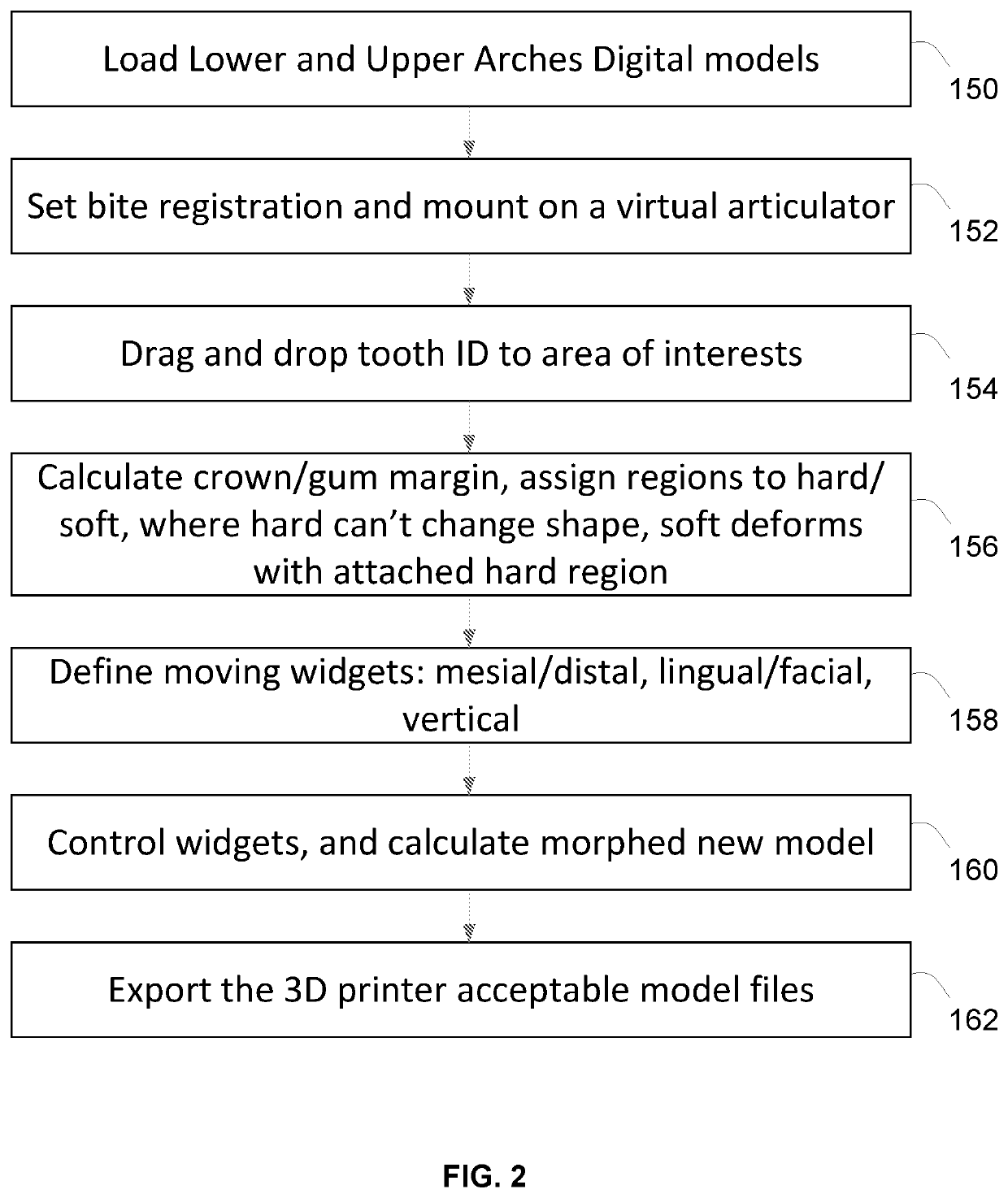
Systems and methods are disclosed for treating teeth to correct for malocclusions. This may be accomplished by applying a series of labels to a digital dental model and applying a rolling ball process to identify tooth boundaries separating one tooth from a neighboring tooth and to also determine the crown / gum margin. The user may further assign regions to the dental model to indicate hard regions and soft regions. With the dental model labeled and defined, the user may then generate a treatment plan for moving the labeled and defined tooth or teeth relative to one another to correct for any malocclusions. Upon approval of the treatment plan, a series of 3D printed dental appliances or aligners to be worn in series by the patient may be fabricated to ultimately move the tooth or teeth to a desired position.

Description

CROSS-REFERENCE TO RELATED APPLICATIONS[0001]This application claims the benefit of priority to U.S. Provisional Application No. 62 / 238,554 filed Oct. 7, 2015, which is incorporated herein by reference in its entirety.FIELD OF THE INVENTION[0002]The present invention relates to methods and apparatus for computerized orthodontics. More particularly, the present invention relates to methods and apparatus for planning orthodontic treatments.BACKGROUND OF THE INVENTION[0003]Orthodontics is a specialty of dentistry that is concerned with the study and treatment of malocclusions which can result from tooth irregularities, disproportionate facial skeleton relationships, or both. Orthodontics treats malocclusion through the displacement of teeth via bony remodeling and control and modification of facial growth.[0004]This process has been traditionally accomplished by using static mechanical force to induce bone remodeling, thereby enabling teeth to move. In this approach, braces having an a...

Claims


Application Information

Patent Timeline
Patent Type & Authority Patents(United States)
IPC IPC(8): A61C7/00G06T7/00A61C7/08A61C9/00G06T11/60G06F30/20A61B6/14A61B6/03G06T19/20A61B6/51
CPCG06F30/20G06T19/20A61C7/002G06T11/60A61C7/08A61C9/004G06T7/0012A61C9/00A61B6/14G06T2207/20036G06T2219/2021G06T2207/10081G06T2210/41A61B6/032G06T2207/30036G06T2219/004A61B1/24A61B6/51
Inventor WEN, HUAFENG
Owner ULAB SYST INC
Learn More