
Ventilated brake disc

a technology of brake discs and ventilation, which is applied in the direction of brake discs, braking elements, braking members, etc., can solve the problems of large heat generation, large temperature gradients across the braking assembly, and deformation or deformation of the brake assembly, so as to maximize the airflow between the disc and the hub, reduce the damage from thermal stress and thermal expansion of the disc, and maximize the effect of ventilation through the dis

Active Publication Date: 2020-04-14
WESTINGHOUSE AIR BRAKE TECH CORP
View PDF50 Cites 4 Cited by
  • Summary
  • Abstract
  • Description
  • Claims
  • Application Information

AI Technical Summary

Benefits of technology

The design effectively reduces wear-based damage, operates more quietly, and maintains performance by optimizing airflow and heat dissipation across the brake disc, minimizing thermal expansion and degradation.

Problems solved by technology

It is well known that significant heat is created as a result of the frictional contact between the brake shoe and brake disc.
The heat may cause thermal expansion of portions of the brake assembly and may cause the brake assembly to deform or degrade following prolonged use.
More particularly, known braking apparatus often do not permit uniform distribution of the generated heat leading to wide temperature gradients across the braking assembly.
Such temperature gradients may cause fissures and cracks to form in the brake disc.
Additionally, cooling airflow is often neither sufficiently uniform nor adequate to counteract the destructive effects of the heat being generated.
Instead, cooling air may actually increase temperature gradients on the brake disc worsening thermal transitional phenomena.
Additionally, a considerable amount of the heat created on the contact surface of the brake element is transferred to the shaft on which the brake disc is mounted.
This transferred heat may cause oxidation to occur on the shaft and / or wheel making replacing brake elements more difficult.
Prolonged heat exposure also alters the centering or calibration of the brake elements and / or drive members further affecting performance of the brake system and wheel.

Method used


Image

  • Ventilated brake disc
  • Ventilated brake disc
  • Ventilated brake disc

Examples


Embodiment Construction

[0049]The following description is provided to enable those skilled in the art to make and use the described embodiments contemplated for carrying out the invention. Various modifications, equivalents, variations, and alternatives, however, will remain readily apparent to those skilled in the art. Any and all such modifications, variations, equivalents, and alternatives are intended to fall within the spirit and scope of the present invention. It is also to be understood that the specific devices illustrated in the attached drawings, and described in the following specification, are simply exemplary embodiments of the invention. Hence, specific dimensions and other physical characteristics related to the embodiments disclosed herein are not to be considered as limiting. For the purpose of facilitating understanding of the invention, the accompanying drawings and description illustrate preferred embodiments thereof, from which the invention, various embodiments of its structures, con...


PUM


Abstract

A friction ring configured to be fixed to a hub at one or more fixation points is provided. The friction ring includes a ring shaped body; an outer surface configured to be contacted by a brake mechanism; an inner surface configured to contact a portion of a hub or axle to impart a braking force thereto; at least one through-hole for receiving a fastener for fixing the friction ring to the hub or axle; and at least two protrusions extending from the inner surface of the friction ring forming a channel. A cross-sectional area of an inflow portion of the channel is smaller than a cross-sectional area of an outflow portion of the channel. A brake assembly including a hub and the fixation ring is also provided.

Description

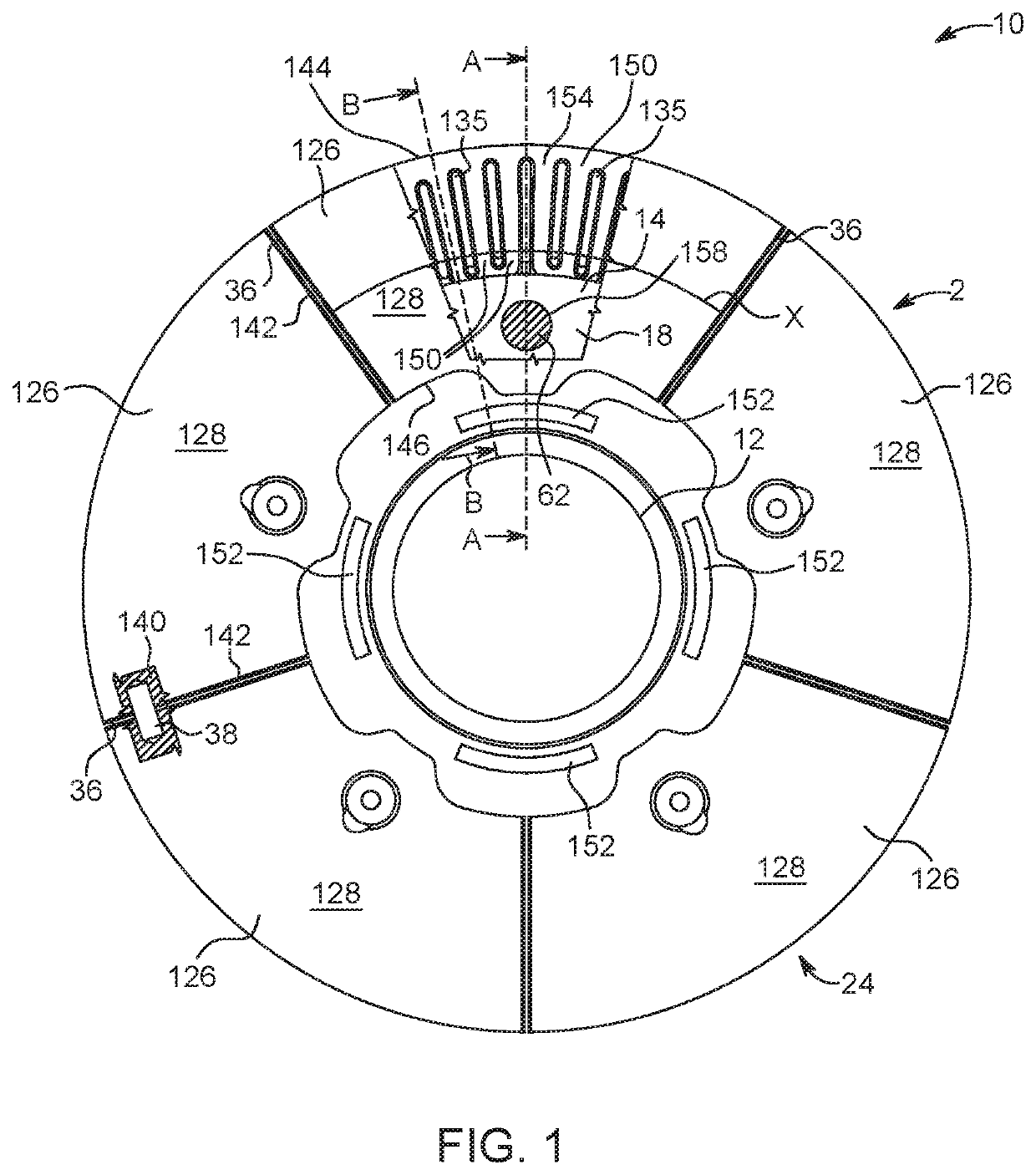
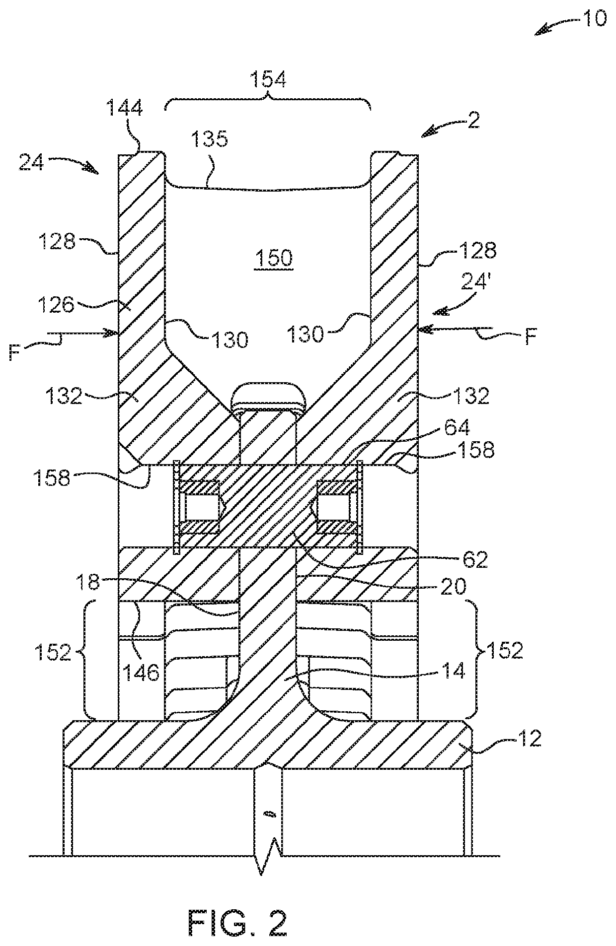
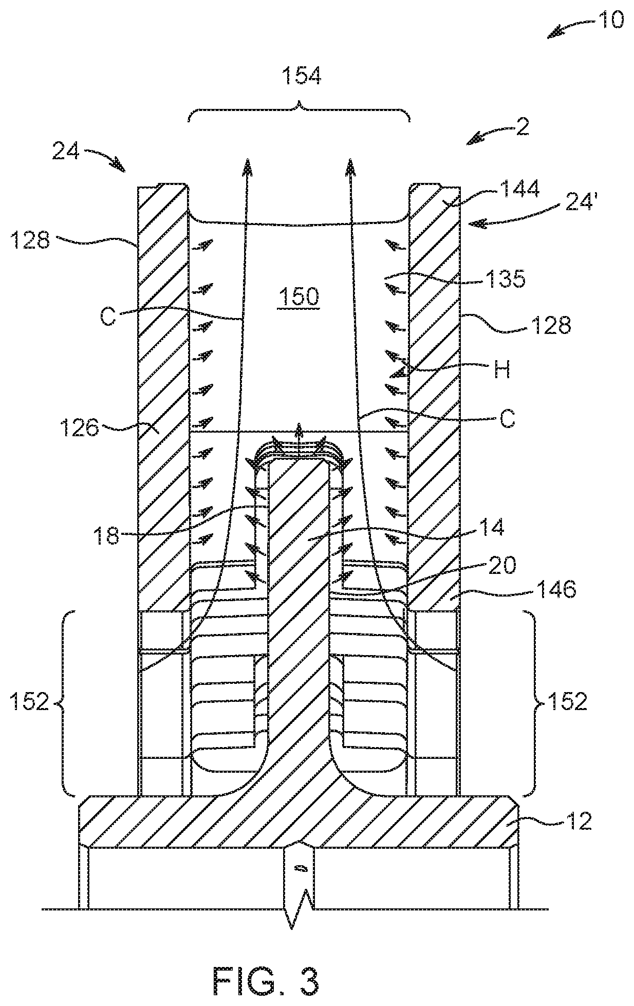
BACKGROUND OF THE INVENTIONField of the Invention[0001]The present disclosure relates to a brake disc for a rotating body, such as a wheel, and, more specifically, to an annular brake disc with a ventilating structure for directing airflow across at least a portion of the disc to transfer heat therefrom.Description of Related Art[0002]Brake discs are affixed to wheels or rotors for the purpose of providing a smooth, hard contact surface that can be contacted by a brake shoe or pad controlled by a brake mechanism, such as a brake jaw. When contact between the disc and shoe or pad is established, friction between the elements is sufficient to slow or stop rotation of the wheel. Disc brakes are commonly used in a variety of applications including, for example, industrial machines, such as cranes and lifts, as well as in conveying installations, such as escalators, elevators, ski-lifts, and the like. Disc brake assemblies are also employed in transport vehicles, such as rail cars, publi...

Claims


Application Information

Patent Timeline
Patent Type & Authority Patents(United States)
IPC IPC(8): F16D65/12F16D65/02
CPCF16D65/128F16D2065/1316F16D2065/1312F16D2065/1392F16D65/121F16D65/123F16D2065/1328F16D65/847F16D2065/1384F16D2065/1388
Inventor BOFFELLI, ROBERTO
Owner WESTINGHOUSE AIR BRAKE TECH CORP
Learn More