
Watercraft with hull ventilation

a technology for watercraft and hulls, applied in vessel construction, special-purpose vessels, transportation and packaging, etc., can solve the problems of increased drag of watercraft, increased instability of watercraft, and complete wetted tunnels, so as to reduce the drag of watercraft, improve the efficiency of watercraft, and maximize the ventilation of the running bottom

Active Publication Date: 2012-07-03
HULL SCI RES LLC
View PDF25 Cites 7 Cited by
  • Summary
  • Abstract
  • Description
  • Claims
  • Application Information

AI Technical Summary

Benefits of technology

"The present invention provides a system to ventilate and wet the vent ducts of a watercraft with a center hull flanked by a pair of amas. The amas and vent ducts are designed to maximize ventilation of the running bottom and improve stability and sea-keeping characteristics of the watercraft. The invention also includes the use of a water plug to reduce viscous drag and improve efficiency of the watercraft. The technical effects of the invention include improved ventilation, reduced viscous drag, and improved stability and sea-keeping characteristics of the watercraft."

Problems solved by technology

Entrapment tunnels of the prior art typically either keep the entire tunnel completely wet or completely dry.
There are drawbacks to both methods.
For example, completely wetted tunnels experience increased drag.
On the other hand, completely dry tunnels cause watercraft instability.
Also for this reason, stepped hulls are not typically used in combination with tunnels, channels, etc., since it is thought that these structures would interfere with the ventilation of the step cavities.

Method used


Image

  • Watercraft with hull ventilation
  • Watercraft with hull ventilation
  • Watercraft with hull ventilation

Examples


Embodiment Construction

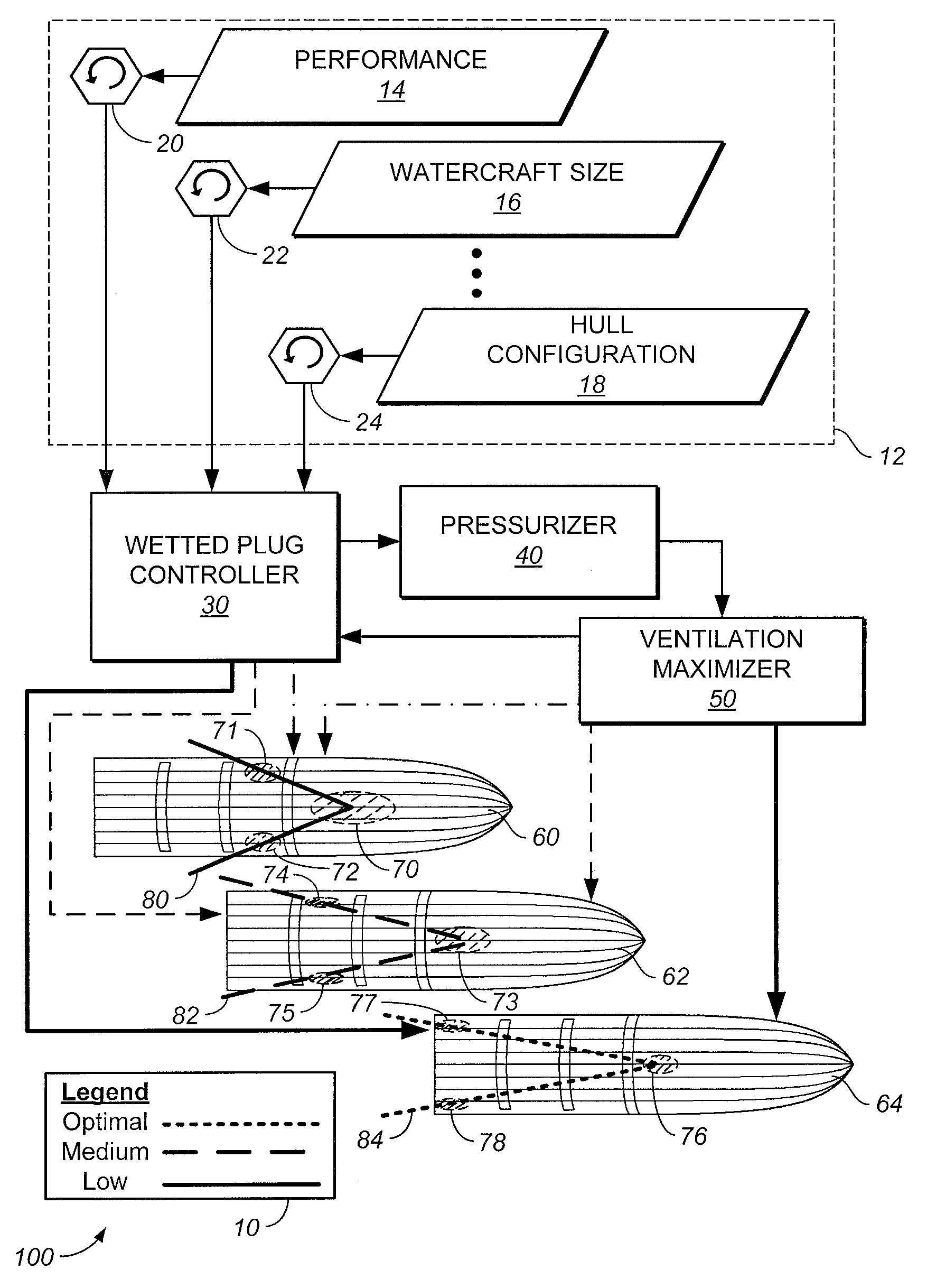
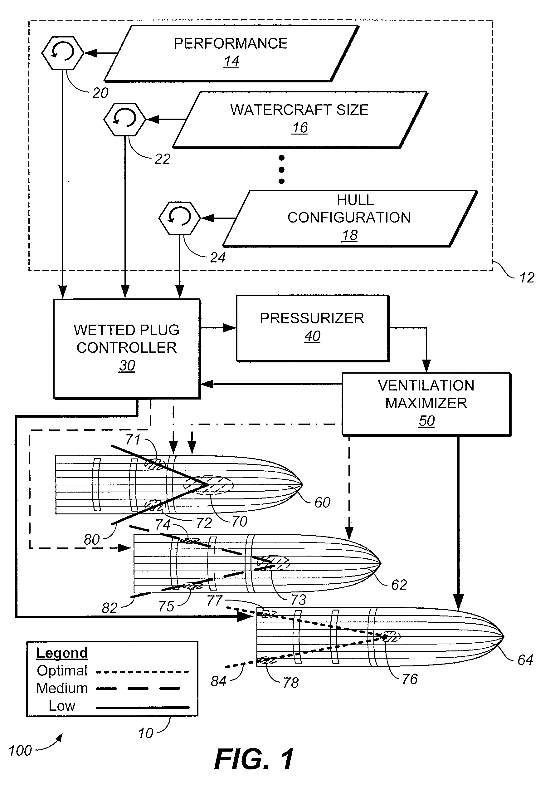
[0026]Referring now to the drawings in detail, FIG. 1 is a diagram illustrating an exemplary system to construct and operate a watercraft, according to at least some embodiments of the invention. The watercraft is configured to operate to both ventilate and wet a pair of vent ducts so as to maximize ventilation on the center hull. Here, system 100 includes input data 12, wetted plug controller 30, pressurizer 40, and ventilation maximizer 50, which are configured to cause the pair of vent ducts (illustrated below) to be variably pressurized as the watercraft 60 travels at low speeds, to when watercraft 62 increases velocity, to when watercraft 64 reaches design speeds. Watercrafts 60, 62, and 64 are bottom plan views.

[0027]The wetted areas of the planing hull can be seen to form a wedge-shaped configuration, that is, one having an apex at the stagnation point where water first makes contact with the hull, and base points formed by the two water plugs. Divergent flow hitting the inbo...


PUM


Abstract

An engine-powered watercraft includes three parallel hulls, namely a center hull with two or more transverse steps, and two smaller outer hulls or amas on either side of the center hull that are configured to form two vent ducts on either side of the center hull, disposed between the center hull sides and the amas. The amas, steps and vent ducts are disposed along the length of the watercraft and are configured to enable high speed capability and to facilitate pressurization of the vent ducts. The pressurized vent duct maximizes ventilation of the running bottom of the watercraft so as to improve efficiency and to reduce drag thereon. The pressurized vent duct creates an area of lift at the widest, aft-most points of the running bottom, which thereby results in improving the transverse and longitudinal stability of the watercraft and in reducing the trim for better seakeeping.

Description

CROSS REFERENCE TO RELATED APPLICATION[0001]This application claims priority under 35 U.S.C. §119(e) from co-pending and commonly-assigned U.S. Provisional Application No. 61 / 241,390, filed on Sep. 10, 2009 by Steven C. H. Loui, et al., entitled “Watercraft with Hull Ventilation,” the subject matter of which is fully incorporated by reference herein.BACKGROUND OF THE INVENTION[0002]1. Field of the Invention[0003]The present invention relates generally to the field of watercraft hull configuration, and more particularly to an engine-powered watercraft having three parallel hulls, with the center of the three hulls being of a v-form having varying deadrise depending on the purpose of the craft and two or more transverse steps, and two outer hulls, i.e., amas, having considerably greater reverse deadrise facing the deadrise of the center hull and vertical outboard surfaces.[0004]2. Description of the Background Art[0005]Entrapment tunnels of the prior art typically either keep the enti...

Claims


Application Information

Patent Timeline
Patent Type & Authority Patents(United States)
IPC IPC(8): B63B1/32
CPCB63B1/38Y02T70/122Y02T70/10
Inventor CAMPBELL, LORNE F.LOUI, STEVEN C. H.PARISH, MEALANI
Owner HULL SCI RES LLC
Learn More