
Rail inspection device and rail inspection system

a technology of inspection device and rail, which is applied in the direction of transportation and packaging, instruments, and ways, can solve the problems of inefficiency of manual operation and oscillation of ceiling transport vehicles, and achieve the effect of efficient inspection and constant level of accuracy

Active Publication Date: 2020-03-31
DAIFUKU CO LTD
View PDF16 Cites 0 Cited by
  • Summary
  • Abstract
  • Description
  • Claims
  • Application Information

AI Technical Summary

Benefits of technology

[0006]A rail inspection device is desired with which an installed state of a first rail and a second rail along a lateral width direction can be inspected efficiently and with a constant level of accuracy without having to depend on a worker.
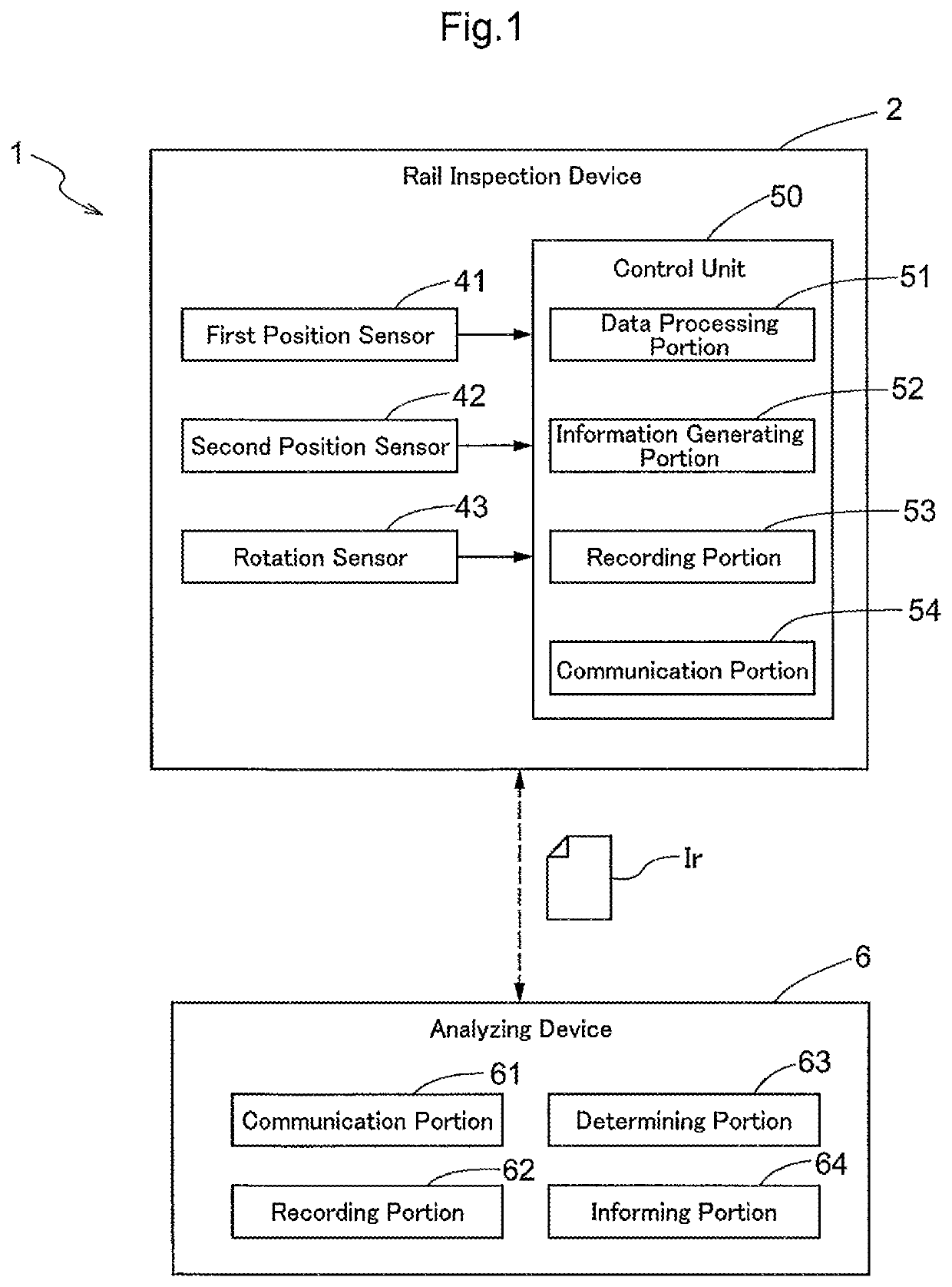
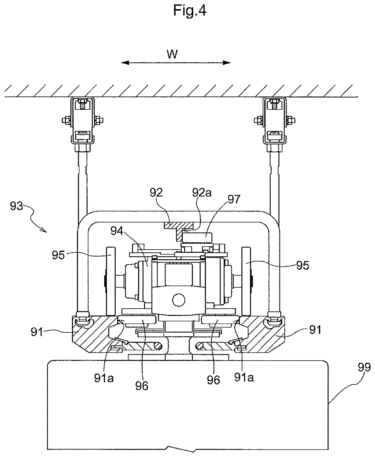
[0008]With this arrangement, a rail inspection device is formed by providing the first position sensor, the second position sensor, and the rotation sensor to the carriage that includes the first roller and the second roller and that has a structure similar to a travel carriage of a common ceiling or overhead transport vehicle. The positions, along the lateral width direction, of the side surfaces of the first rail or the second rail can be obtained easily with the first position sensor and the second position sensor simply by causing the rail inspection device that is designed to be similar to a travel carriage of such a common ceiling transport vehicle to travel along the first rail and the second rail. And the distance between the first rail and the second rail along the lateral width direction can be calculated, as the installed state of the first rail and the second rail, from the positions of the side surfaces of the first rail and the second rail along the lateral width direction. In addition, by measuring the rotation angle of one of (a) one of the wheels, (b) the first roller, and (c) the second roller with at least one rotation sensor, the position along the rail extending direction can be calculated from the rotation angle. And the position along the rail extending direction, and the distance between the first rail and the second rail along the lateral width direction can be associated with each other. Therefore, the lateral distance (distance along the lateral width direction) between the first rail and the second rail at any position along the rail extending direction can be continuously measured in a relatively short period of time. Thus, inspection efficiency can be improved. Because the inspection only requires causing the rail inspection device to travel along the first rail and the second rail with very little dependency on a worker's measurement skills, a constant level of inspection accuracy can be maintained without having to rely on a worker.

Problems solved by technology

In such an article transport facility, oscillations may occur in ceiling transport vehicles during traveling if the travel rails or the guide rail are not installed properly.
This method involving such manual operation is not only inefficient, but also depends highly on the worker's skill to take measurements, making it more likely to have variations in accuracy in the inspection.

Method used


Image

  • Rail inspection device and rail inspection system
  • Rail inspection device and rail inspection system
  • Rail inspection device and rail inspection system

Examples


Embodiment Construction

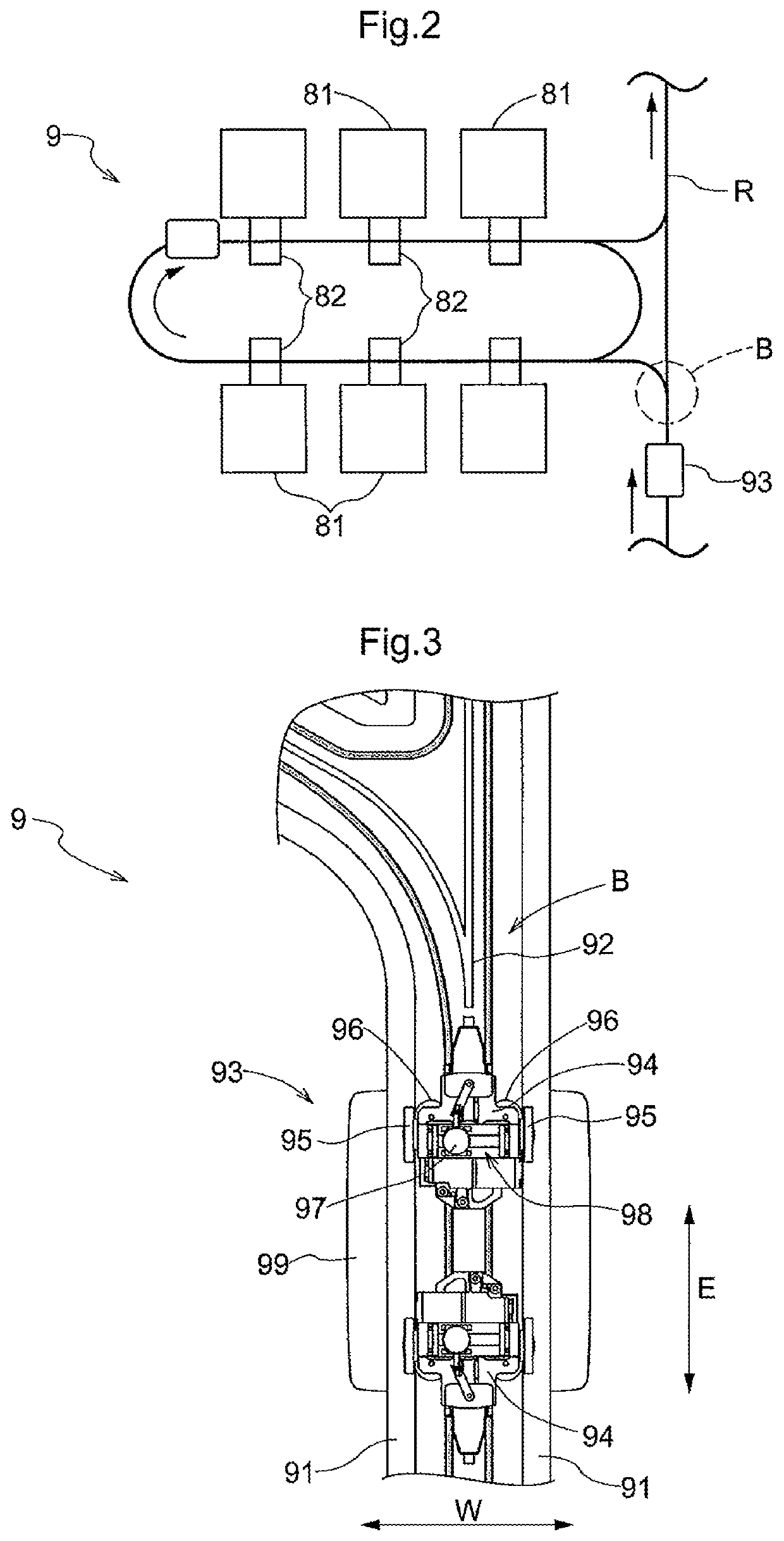
[0022]Embodiments of a rail inspection device and a rail inspection system that uses the rail inspection device are described with reference to the attached drawings. In the present embodiment, an example is described in which a rail inspection system 1 and a rail inspection device 2 for inspecting an installed state of a travel rail 91 and a guide rail 92 installed in an article transport facility 9 provided in a clean room of, for example, a semiconductor substrates processing factory, etc.

[0023]As shown in FIG. 1, the rail inspection system 1 of the present embodiment includes a rail inspection device 2, and an analyzing device 6 which is signally connected to the rail inspection device 2 for exchanging information. The rail inspection device 2 is configured to travel along the travel rails 91 and the guide rail 92 to obtain data, and to transmit the obtained data (inspection result information Ir described below) to the analyzing device 6. The analyzing device 6 determines the p...


PUM


Abstract

A rail inspection device comprises a carriage having wheels, a first roller in contact with a side surface of a first rail, a second roller in contact with a side surface of a second rail, a first position sensor configured to detect a position of a side surface of the first rail or an outer surface of the first roller, a second position sensor configured to detect a position of a side surface of the second rail or an outer surface of the second roller, and at least one rotation sensor each configured to detect a rotation angle of a wheel, the first roller, or the second roller.

Description

CROSS-REFERENCE TO RELATED APPLICATION[0001]This application claims priority to Japanese Patent Application No. 2016-201209 filed Oct. 12, 2016, the disclosure of which is hereby incorporated in its entirety by reference.FIELD OF THE INVENTION[0002]The present invention relates to a rail inspection device and a rail inspection system.BACKGROUND ART[0003]Ceiling or overhead transport vehicles which are sometimes used in, for example, an article transport facility transport articles by traveling along a pair of travel rails and a guide rail installed above the travel rails. In such an article transport facility, oscillations may occur in ceiling transport vehicles during traveling if the travel rails or the guide rail are not installed properly. Therefore, it is important to have the travel rails and the guide rail properly installed. To this end, it is preferable that the installed state of the rails can be inspected simply and reliably. A rail inspection device used for this purpose...

Claims


Application Information

Patent Timeline
Patent Type & Authority Patents(United States)
IPC IPC(8): E01B35/04B61B3/02B61K9/08
CPCE01B35/04B61K9/08B61B3/02B61D15/12G01D21/02G01B21/16
Inventor HORII, TAKAHIRONAKANO, YOSHIHIRO
Owner DAIFUKU CO LTD
Learn More