
Device and method for high dose per pulse radiotherapy with real time imaging

a high-dose per pulse, real-time imaging technology, applied in the field of radiotherapy system, can solve the problems of not being able to perform radiography at each irradiation step, not being able to synchronize imaging system and feedback control, etc., to achieve the effect of improving the treatment plan

Active Publication Date: 2020-03-31
FYZIKALNI USTAV AV CR V V I
View PDF9 Cites 18 Cited by
  • Summary
  • Abstract
  • Description
  • Claims
  • Application Information

AI Technical Summary

Benefits of technology

The present invention is a system that allows for highly effective treatment by delivering a high dose per pulse to a target region of the body. The system uses an imaging system to monitor the position of the target region during treatment and can adapt and improve the treatment plan accordingly. The system can use a synchronized imaging system to better understand how the target region has been irradiated and improve the dose delivery in future pulses. The target region images are analyzed after each radiation pulse and used in combination with the data relative to the radiation pulses to improve the treatment plan. Overall, this system allows for precise treatment with just a few radiation pulses and reduces the risk of complications.

Problems solved by technology

Treatments with these devices usually last at least few minutes.
Using radio frequency accelerators, due to the low dose per pulse and to the high number of pulses needed, it is not feasible to perform radiography at each irradiation step.
The disclosed device produces ultra-short radiation pulses (50 MeV), but it is lacking a synchronized imaging system and a feedback control that exploits the treatment effectiveness due to the shortness of the radiation pulses.

Method used


Image

  • Device and method for high dose per pulse radiotherapy with real time imaging
  • Device and method for high dose per pulse radiotherapy with real time imaging
  • Device and method for high dose per pulse radiotherapy with real time imaging

Examples


Embodiment Construction

[0100]Details of the present invention are further illustrated using the following exemplary embodiments. However, these examples should not be construed as limiting the scope of the claimed invention. Unless indicated otherwise, the embodiments shown in the figures are independent and may be used separately or in combination.

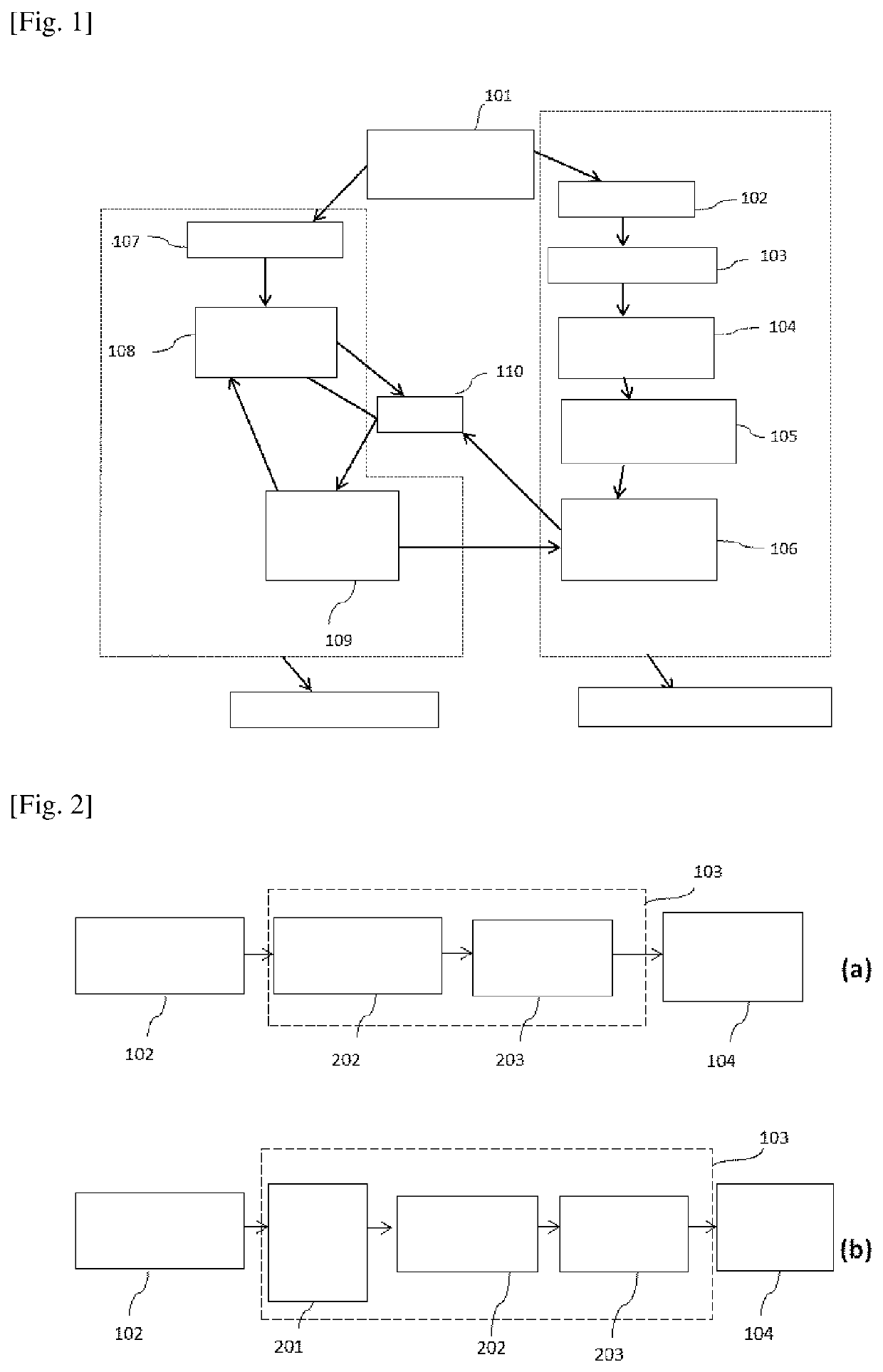
[0101]FIG. 1 schematically represents one possible embodiment of the system, in this specific case using x-ray imaging and a laser plasma electron accelerator. The synchronization system 101 synchronizes, with a time jitter lower than 200 ms, the emission of an x-ray pulse from the x-ray machine 107 and the emission of a laser pulse from the laser system 102. The laser pulse is transported through the laser transport 103, and then focused by the laser focusing system 104 into the plasma electron accelerator 105. Each single electron beam generated in the plasma electron accelerator 105 goes into the radiation beam delivery system 106, which operates on each ele...


PUM


Abstract

A radiotherapy system comprising at least one pulsed radiation source, at least one imaging system, a control system, and a synchronization system is disclosed. The pulsed radiation source deposits high dose radiation pulses to a target region inside the patient; simultaneously the imaging system is used to monitor the target region, synchronized by the synchronization system. The dose per radiation pulse is high enough to deposit, within few pulses, 1 Gy at a depth of at least 1 cm in water. At each irradiation time step, the pulsed radiation source delivers short pulses of radiation (<1 ms) and the imaging system performs a snapshot of the position, and eventually the shape, of the target region during the irradiation time, with a time resolution better than 200 ms. Being both the pulsed radiation source and imaging system synchronized by the synchronization system with less than 200 ms jitter, this system allows for very precise reconstruction of the map of the dose deposited into the target region.

Description

TECHNICAL FIELD[0001]The invention relates to a radiotherapy system which allows the monitoring of the position of the target region during the treatment and thus allowing effective radiotherapeutic treatment.BACKGROUND ART[0002]Radiotherapy is an important treatment for many types of cancer. This technique relies on the use of radiation sources to deliver dose to a target region within the patient's body. Furthermore, radiotherapy is not restricted only to cancer treatment, but can be applied in general to deliver dose to a target region within the patient's body as in the case, for example, of radiosurgery.[0003]In the state of the art, radiotherapy is, in most of the cases, performed using radio frequency accelerators, which are devices capable of delivering electron or gamma beams with energy typically in the range 6-30 MeV. Due to their technology, these devices usually deliver very wide beams on the order of 10×10 cm2 and a dose rate of few Gy / min. Typically, such devices deli...

Claims


Application Information

Patent Timeline
Patent Type & Authority Patents(United States)
IPC IPC(8): A61N5/10A61N5/06G01J11/00A61N5/067G01T1/29
CPCA61N5/06A61N5/1071A61N5/1075A61N5/1067G01J11/00A61N5/1039G01T1/29A61N2005/1089A61N2005/067A61N2005/109A61N2005/1088A61N2005/1061A61N5/067
Inventor GRITTANI, GABRIELE MARIALEVATO, TADZIOLAZZARINI, CARLO MARIAKORN, GEORG
Owner FYZIKALNI USTAV AV CR V V I
Learn More