Light-conductive optical system, especially for a light device of a vehicle

a technology of optical system and light guide, which is applied in the direction of instruments, mechanical equipment, lighting and heating apparatus, etc., can solve the problems of reducing the light efficiency affecting the shape of the light guide, and unable to efficiently use the light emitted by the light sour

Active Publication Date: 2020-03-24
PO LIGHTING CZECH SRO
View PDF27 Cites 0 Cited by
  • Summary
  • Abstract
  • Description
  • Claims
  • Application Information

AI Technical Summary

Problems solved by technology

A common drawback of known light guides used for light devices of motor vehicles is the fact that a certain part of the light emitted by the light sources is not used or that the required shape of the output surface of the light guide does not support efficient use of the emitted light, which reduces the light efficiency of the light guide.
However, a disadvantage of this solution is that efficient use of light emitted by the light sources is not made possible because maximum binding of light rays emitted by the light source is not enabled.
Another disadvantage is the shape of the light guide, which is not adaptable to the mechanical design of the light device.
The first disadvantage of this solution is uneven distribution of light intensity on the output surface of the light-guiding plate as at least two reflective surfaces of the reflective means have a common edge in each case, i.e. they are not spatially offset, i.e. they have a constant shape of a sector of a circle, and on the output surface, patterns are projected in the form of discontinuous regions with an unsymmetrical shape that do not respect the shape of the output surface.
Another disadvantage is that the size of the reflective surfaces of the reflective means cannot be changed to adapt the optical concept to the mechanical design of the lighting device.
The third disadvantage is the fact that the ratio of the width to the thickness of the light guide is fixed and the shape of the collimator determines the shape of the reflective means and thus the shape of projected patterns on the output surface, which makes redistribution of the intensity of light emitted from individual reflective surfaces of the reflective means through the reflective means impossible and it is not possible to divide light into two separate light guides either.
However, this requirement encounters several technical problems.
A disadvantage of this solution is the fact that the dimensions of the light guide must be selected in such a way that either the output surface is thin, but the light efficiency of the light guide is not high, or the light efficiency is high and the output light surface is not as thin.
Another disadvantage of this solution is the fact that the light beam gets divided especially over the center of the collimating element, which may cause a loss of efficiency and even small production defects / deviations can result in a significant loss of efficiency.

Method used


Image

  • Light-conductive optical system, especially for a light device of a vehicle
  • Light-conductive optical system, especially for a light device of a vehicle
  • Light-conductive optical system, especially for a light device of a vehicle

Examples


Embodiment Construction

OF EMBODIMENTS OF THE INVENTION

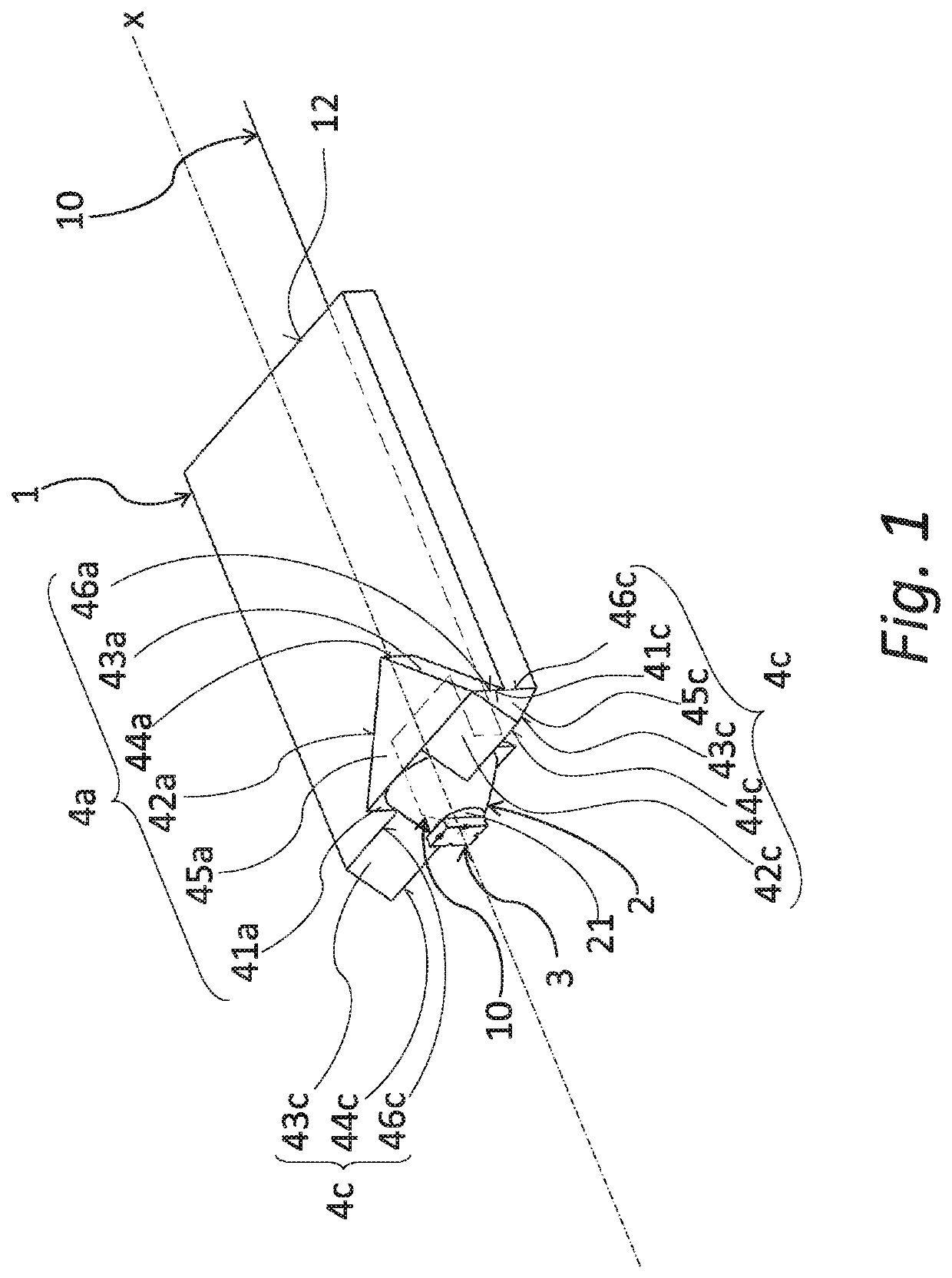
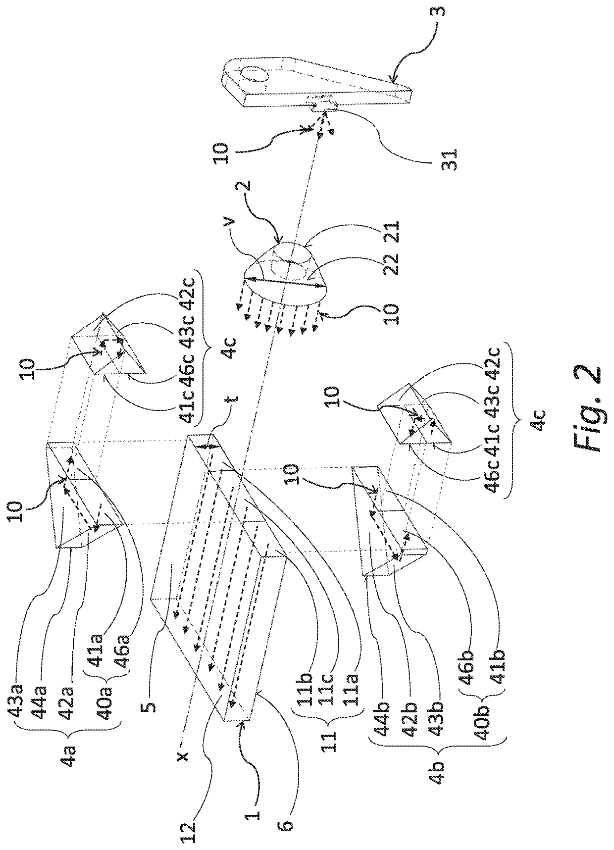
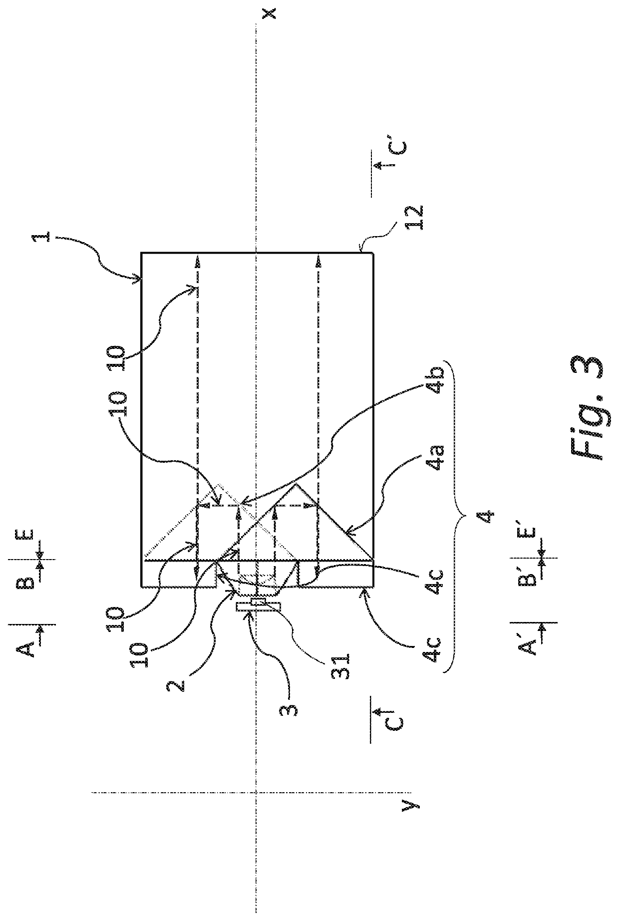
[0045]FIGS. 1, 2, 3, 4a, 4b, 5, 6 and 7 show the first embodiment example of a light-conductive optical system according to the present invention, which comprises a planarly shaped light guide 1 having the shape of a plate and a collimating element 2 having the form of a rotary body and a light-conductive reflective array 4 of four reflective means 4a, 4b, 4c. The light guide 1, the collimating element 2 and the reflective means 4a, 4b, 4c preferably form an integral body that is made from an optically transparent material and is used to guide light rays 10 emitted by the light unit 3 comprising at least one light source 31, e.g. LED.

[0046]The collimating element 2 is oriented with its input surface 21 towards the light source 31 to bind light rays 10 emitted in the horizontal direction and with its output surface 22 it is oriented towards the input surface 41a of the top reflective means 4a, towards the input surface 41b of the bottom reflective means...


PUM

PropertyMeasurementUnit
diameteraaaaaaaaaa
thicknessaaaaaaaaaa
angleaaaaaaaaaa

Abstract

The light-conductive optical system comprises a planarly shaped light guide (1) made from an optically transparent material with an associated light unit (3) and a collimating element (2). The light guide (1) comprises an output surface (12) for the output of light rays (10) and a binding surface (11) to bind light rays (10) to the light guide (1). The output surface (12) and the binding surface (11) are situated on surfaces that transversally connect the top (5) and bottom surface (6) of the light guide (1) and the binding surface (11) comprises a partial surface (11c) situated opposite the output surface (22) of the collimating element (2) and a lateral partial surface (11a, 11b) at one or both sides of the partial surface (11c). The height (v) of the output surface (22) is bigger than the thickness (t) of the light guide (1) so the output surface (22) reaches above the top surface (5) and / or below the bottom surface (6) of the light guide (1) with its overlapping part (8, 9). The light guide (1) is, for each overlapping part (8, 9), fitted with at least a pair of reflective means (4a, 4b; 4c) comprising the first reflective means (4a, 4b) situated opposite the overlapping part (8, 9) to bind at least a part of light rays (10) exiting from the overlapping part (8, 9) and to reflect them to the second reflective means (4c) adapted to direct light rays (10) against the lateral partial surface (11a, 11b).

Description

RELATED APPLICATIONS[0001]This application claims the priority benefit of Czech Patent Application Serial No. PV 2017-541 entitled “A light-conductive optical system, especially for a light device of a vehicle,” filed Sep. 14, 2017, the entire disclosure of which is incorporated herein by reference.FIELD OF THE INVENTION[0002]The invention relates to a light-conductive optical system, especially for a light device of a vehicle, that comprises a light guide and a collimating element to conduct light emitted by a light source.BACKGROUND INFORMATION[0003]A common drawback of known light guides used for light devices of motor vehicles is the fact that a certain part of the light emitted by the light sources is not used or that the required shape of the output surface of the light guide does not support efficient use of the emitted light, which reduces the light efficiency of the light guide. In the field of the design of light guides and light-guiding systems, there is a permanent effor...

Claims


Application Information

Patent Timeline
Patent Type & Authority Patents(United States)
IPC IPC(8): F21S41/00F21S41/32F21S43/14F21S43/239F21S43/40F21S43/249F21V8/00F21S41/24F21S43/243F21S43/241F21S41/151F21S41/143F21S43/31F21S43/15
CPCG02B6/0031G02B6/0045F21S41/143G02B6/0023G02B6/003F21S41/24F21S43/40F21S43/14G02B6/0066F21S43/15F21S43/249F21S41/151F21S43/241F21S41/322F21S43/239F21S43/315F21S43/243G02B6/0028G02B6/0078G02B6/0018F21S43/235G02B6/002
Inventor GLOSS, TOMASHRUSKA, JAKUBSIMURDA, VITHANKO, JAN
Owner PO LIGHTING CZECH SRO
Why Eureka
Try Eureka