Eureka AIR delivers breakthrough ideas for toughest innovation challenges, trusted by R&D personnel around the world.

Capacitive sensor array for dental occlusion monitoring

a sensor array and capacitive technology, applied in the field of dental surgery, can solve the problems of affecting the reliability, lack of repeatability and sensitivity, and quantitative indicators employing electro-optic and resistive techniques, and achieve the effect of reducing the electromagnetic interaction

Active Publication Date: 2020-03-24
ECOLE POLYTECHNIQUE FEDERALE DE LAUSANNE (EPFL)
View PDF10 Cites 0 Cited by
  • Summary
  • Abstract
  • Description
  • Claims
  • Application Information

AI Technical Summary

Benefits of technology

[0018]In one embodiment, the device is characterized in that it further comprises at least two shield layers embedded in the soft substrate located respectively above and under the sensor and connected to ground, wherein said shield layers are shaped as to reduce the electromagnetic interaction between a body part and the transmission conductive lines of the sensor due to a proximity effect.
[0028]In one embodiment, the device is characterized in that it further comprises at least two shield layers embedded in the soft substrate located respectively above and under the sensor and / or the shielding pads and connected to ground, wherein said shield layers are shaped as to reduce the electromagnetic interaction between a body part and the transmission conductive lines of the sensor due to a proximity effect.

Problems solved by technology

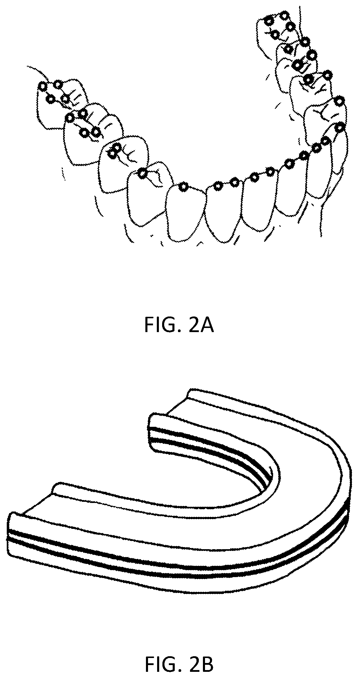
Therefore, their main limitation is that they provide just a qualitative indication of location and number of tooth contacts without any information about the amount of jaw unbalance and the influence of each contact point.
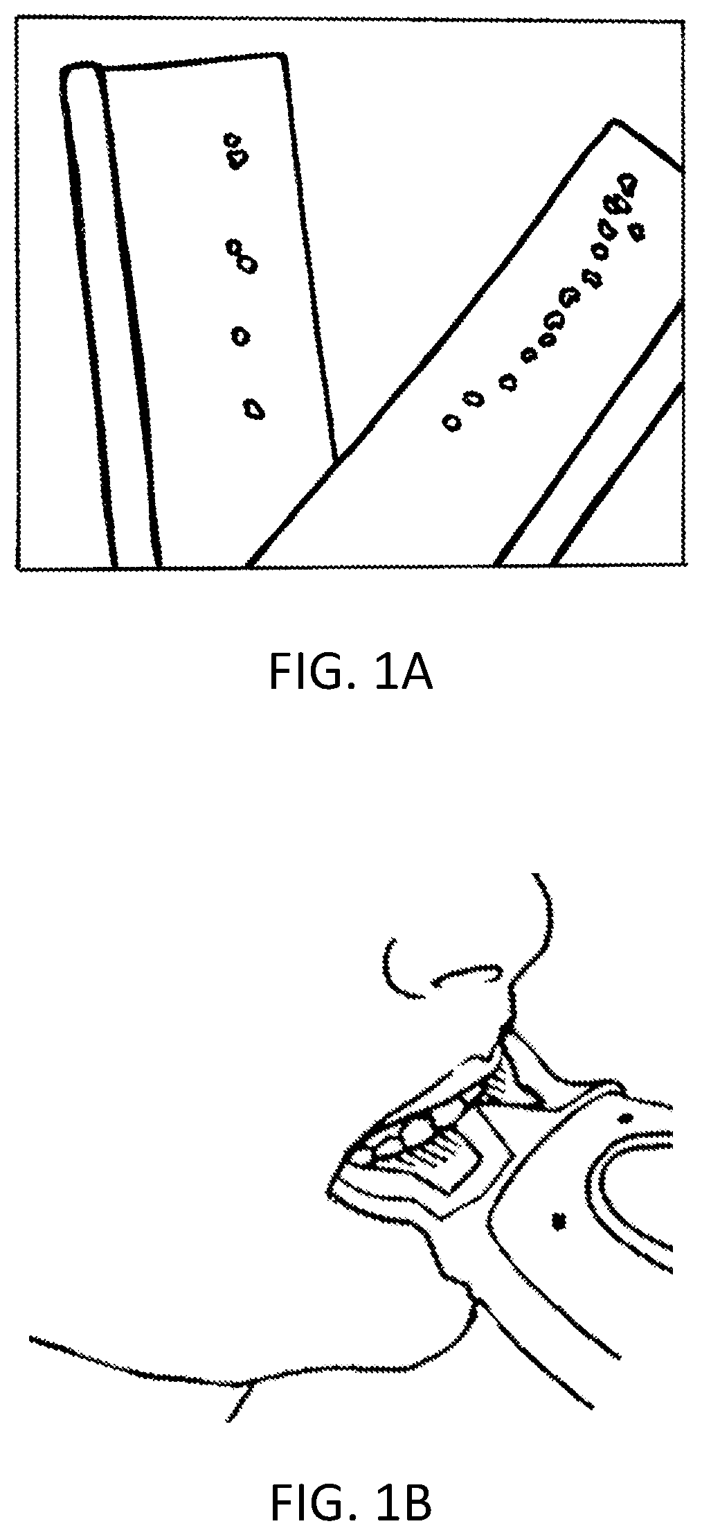
Quantitative indicators employing electro-optic and resistive techniques, such as the TekScan® (see FIG. 1b) pressure measurement system, lack repeatability and sensitivity.
Due to their stiffness and high thickness, this kind of device affects negatively the reliability of the results, providing an over-detection of contact points and generating a proprio-receptive response.

Method used


Image

  • Capacitive sensor array for dental occlusion monitoring
  • Capacitive sensor array for dental occlusion monitoring
  • Capacitive sensor array for dental occlusion monitoring

Examples


Embodiment Construction

[0046]The present disclosure may be more readily understood by reference to the following detailed description presented in connection with the accompanying drawing figures, which form a part of this disclosure. It is to be understood that this disclosure is not limited to the specific conditions or parameters described and / or shown herein, and that the terminology used herein is for the purpose of describing particular embodiments by way of example only and is not intended to be limiting of the claimed disclosure.

[0047]As used herein and in the appended claims, the singular forms “a,”“and,” and “the” include plural referents unless the context clearly dictates otherwise. Thus, for example, reference to “a sensor” includes a plurality of such sensors and reference to “a transmission conductive line” includes reference to one or more conductive lines, and so forth.

[0048]Also, the use of “or” means “and / or” unless stated otherwise. Similarly, “comprise,”“comprises,”“comprising”“includ...


PUM

PropertyMeasurementUnit
capacitanceaaaaaaaaaa
thicknessaaaaaaaaaa
conductiveaaaaaaaaaa

Abstract

The invention relates to devices, systems and methods exploiting capacitive means for monitoring and analysing teeth-related parameters in a subject, such as the dental occlusion profile and / or the load / force applied upon clenching. The device comprises a body such as a bite fork or bite splint, capacitive sensor(s) incorporated within a soft substrate reversibly deformable once bitten by a subject and a micro-controller unit. The teeth contact points and forces applied upon occlusion are measured via the sensors, delivered to and re-elaborated by the micro-controller unit and possibly sent and visualized in a graphical / numerical fashion on e.g. a display screen.

Description

CROSS REFERENCE TO RELATED APPLICATIONS[0001]The present application is a U.S. national stage application of PCT / IB2015 / 053786 filed on May 22, 2015 designating the United States, and claims foreign priority to International patent application PCT / IB2014 / 061728 filed on May 26, 2014, the contents of both documents being herewith incorporated by reference in their entirety.TECHNICAL FIELD[0002]The present invention is in the field of dentistry. It more precisely relates to the qualitative and quantitative monitoring of dental occlusion.BACKGROUND ART[0003]During the last years the engineering approach in dentistry is getting more importance. This is certainly due to the continuous improvements in complex surgical techniques. Occlusion issues have been highlighted in a significant number of scientific publications because of their consequences on health such as teeth damages and fractures, dental implants failure, headaches, back pain and postural problems. Monitoring of dental occlus...

Claims


Application Information

Patent Timeline
Patent Type & Authority Patents(United States)
IPC IPC(8): A61C19/05G01L1/14A61B5/00A61B5/22
CPCA61B5/4542G01L1/148A61B5/228A61B5/4547G01L1/146A61B5/682A61C19/05A61B2562/0247A61B2562/046
Inventor BOROTTO, MARCOLETIZIA, MARCO
Owner ECOLE POLYTECHNIQUE FEDERALE DE LAUSANNE (EPFL)
Why Eureka
Eureka Blog
Learn More