Hearing instrument comprising two antennas

a technology of antennas and hearing devices, applied in the field of hearing instruments, can solve the problems of relatively high power consumption of bluetooth links between two hearing devices, difficulty in meeting power consumption or electromagnetic emissions requirements, and limited physical dimensions of hearing instruments, so as to reduce the number of bluetooth links, maintain or optimize the quality and power efficiency of the respective wireless link to the respective external device, and reduce the effect of electromagnetic interaction

Active Publication Date: 2016-11-01
SONOVA AG
View PDF13 Cites 2 Cited by
  • Summary
  • Abstract
  • Description
  • Claims
  • Application Information

AI Technical Summary

Benefits of technology

[0013]The invention is beneficial in that, by providing a first part of the hearing instrument with a first antenna to be located substantially within the ear channel and by providing a second part of the hearing instrument with a second antenna to be located outside the ear channel at the user's head, with the first antenna being operated in a first frequency range and the second antenna being operated in a second frequency range higher than the first frequency range, the adsorption of electromagnetic waves by human tissue reduces electromagnetic interaction between the two antennas, while quality and power efficiency of the respective wireless link to the respective external device is maintained or optimized; this makes use of the fact that low frequency radiation is less strongly adsorbed by human tissue than high frequency radiation.
[0014]Because of the strong interaction between human tissue and high frequency electromagnetic waves it might be desired to reduce the number of Bluetooth links in vicinity of the body for health reasons. The invention is beneficial because it allows the electromagnetic radiation near the human body to be reduced in comparison to other wireless solutions.

Problems solved by technology

At the same time, their physical dimensions are generally very limited.
The requirements regarding power consumption or electromagnetic emissions are therefore more challenging than for hearing instruments in general.
While Bluetooth technology is widely available, one disadvantage is the relatively high power consumption of a Bluetooth link between two hearing devices.

Method used


Image

  • Hearing instrument comprising two antennas
  • Hearing instrument comprising two antennas
  • Hearing instrument comprising two antennas

Examples


Embodiment Construction

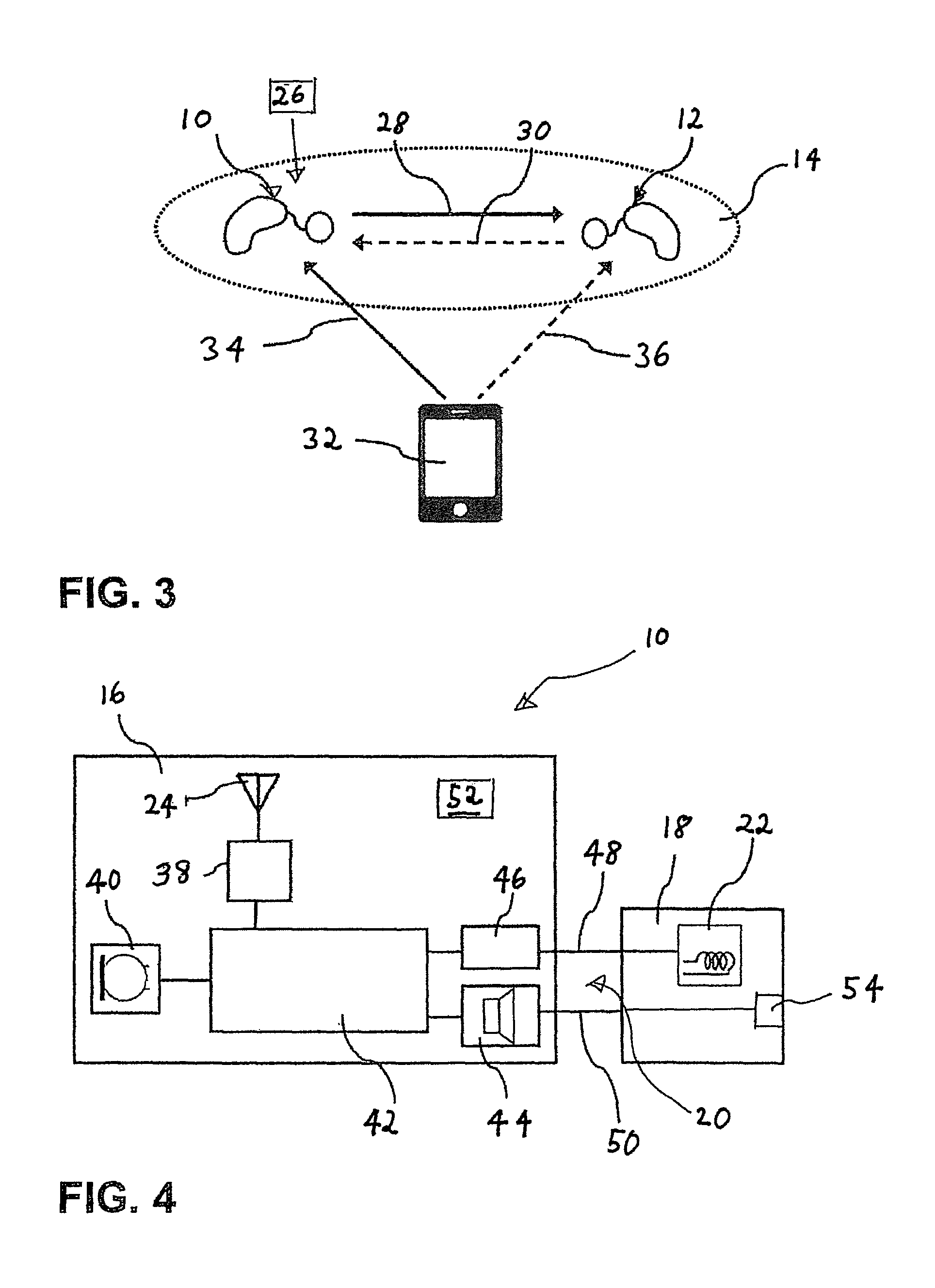
[0023]A hearing instrument of the present invention comprises a first part to be located at least in part in the ear canal and comprising a first antenna to be located substantially within the ear canal and a second part to be worn outside the ear canal at the concha and comprising a second antenna to be located outside the ear canal; typically, the first part is designed as an ITE part and the second part is designed as a BTE part. However, the second part also may be positioned in front of the concha or be attached at the concha.

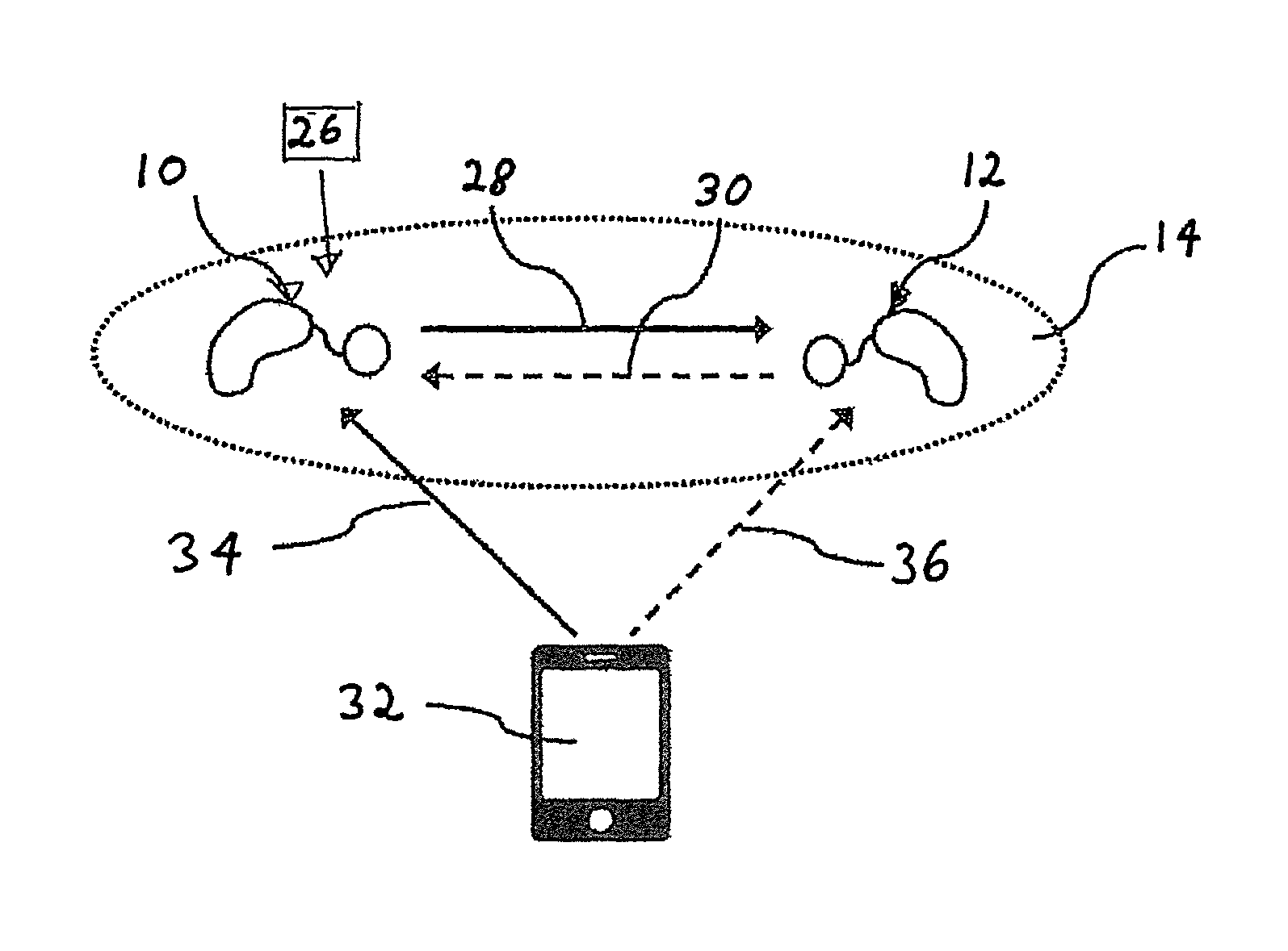
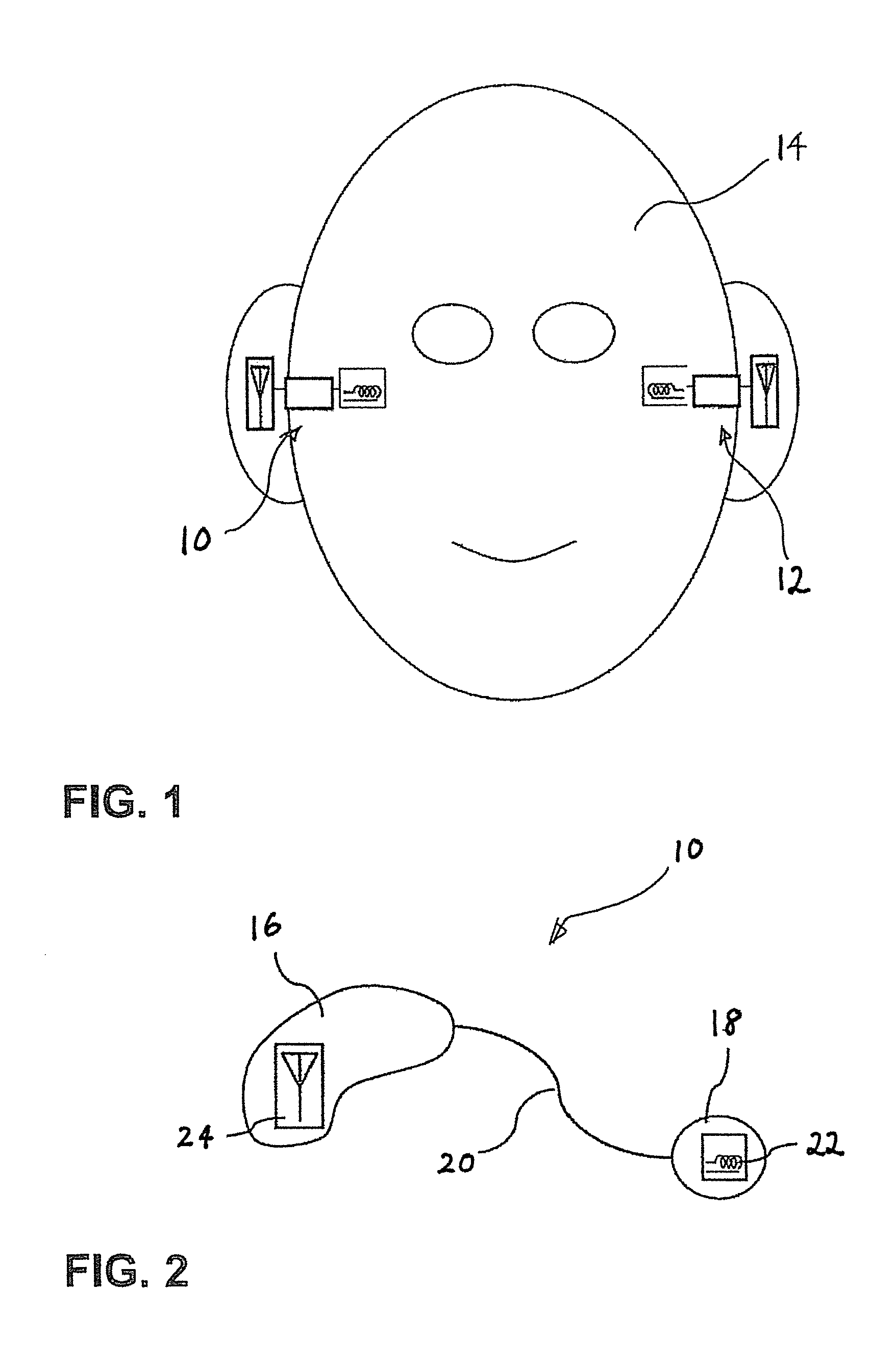
[0024]FIG. 1 is a schematic illustration of an example of a binaural system comprising a first hearing instrument 10 and a second hearing instrument 12, each one at one ear of a user's head 14.

[0025]According to FIG. 2, the hearing instrument 10 comprises a BTE part 16 and an ITE part 18, which are connected via a connection 20 which provides for an electrical wire connection and also may comprise, in case that the ITE part does not comprise a loudspeaker,...


PUM


Abstract

A hearing instrument to be worn at an ear of a user, having a first part (18) to be located at least in part in the ear canal, a first antenna (22) to be located substantially within the ear canal, a second part (16) to be worn outside the ear canal at the concha and a second antenna (24) to be located outside the ear canal, wherein the first antenna is to be operated by a first transceiver (46) in a first frequency range and the second antenna is to be operated by a second transceiver (38) in a second frequency range which is higher than the first frequency range.

Description

BACKGROUND OF THE INVENTION[0001]1. Field of the Invention[0002]The invention relates a hearing instrument comprising a first part to be worn at least in part within the ear canal (typically designed as an ITE (“in-the-ear”) part) and a second part to be worn outside the ear canal at the concha (typically designed as a BTE (“behind-the-ear”) part), with the hearing instrument being suitable for wireless communication.[0003]2. Description of Related Art[0004]Hearing instruments may be designed for wireless communication with various devices, such as for communication with another hearing instrument that is located at the other ear of the user, a body worn relay device forwarding an audio signal to the hearing instrument, a remote control, a mobile phone, a TV set gateway, a wireless microphone, etc. Communication to different types of such devices may occur in different frequency bands: for example, communication between body worn devices typically takes place via an inductive link o...

Claims


Application Information

Patent Timeline
Patent Type & Authority Patents(United States)
IPC IPC(8): H04R25/00H01Q21/28H01Q1/27H01Q1/22
CPCH04R25/556H01Q1/273H01Q21/28H04R25/552H04R25/554H01Q1/2291H04R25/305H04R25/558H04R2225/021H04R2225/025H04R2225/51H04R2225/55H04R2460/03H04R2225/0216
Inventor RIEPENHOFF, MATTHIAS
Owner SONOVA AG
Why Eureka
Try Eureka