
Resonator, unit and oscillator

a technology of resonators and oscillators, applied in the field of resonators, can solve the problems of large series resistance, reduced quality factor, low stability of resonators, etc., and achieve the effects of small series resistance, small motional inductance lm, and strong

Active Publication Date: 2020-03-17
PIEDEK TECHN LAB
View PDF16 Cites 3 Cited by
  • Summary
  • Abstract
  • Description
  • Claims
  • Application Information

AI Technical Summary

Benefits of technology

This patent is about a miniature unit with a tuning fork resonator, which is strong against shock. The unit has a small series resistance, a small motional inductance, and a small capacitance ratio. The resonator is made by using a quartz crystal tuning fork and has a high stability of frequency, high quality factor, and a small mounting area. The unit is easy to manufacture and has high shock-proof properties. The patent also includes a relationship between the size of the frame and the distance between the frames to improve the stability of the resonator. Overall, this patent describes a miniature, strong, and stable tuning fork resonator for use in oscillators and other electronic devices.

Problems solved by technology

Heretofore, however, it has been impossible to obtain an electronic apparatus comprising a smaller quartz crystal oscillator with a miniature quartz crystal tuning fork resonator of the prior art having a frequency of high stability, a small series resistance and a high quality factor.
As a result of which, the resonator has a frequency of low stability, a large series resistance and a reduced quality factor.

Method used


Image

  • Resonator, unit and oscillator
  • Resonator, unit and oscillator
  • Resonator, unit and oscillator

Examples


first embodiment

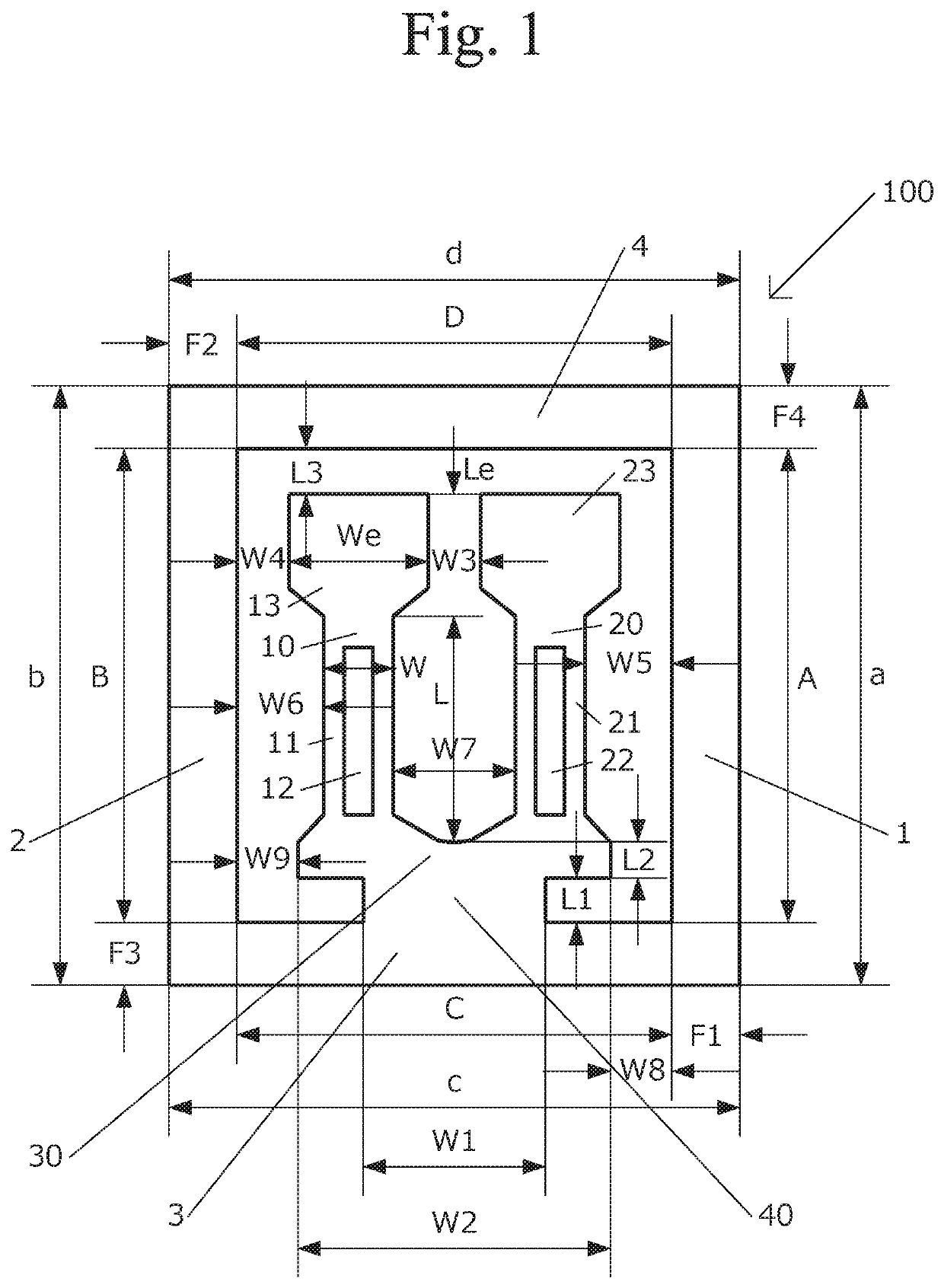
[0042]FIG. 1 shows a plan view of a tuning fork resonator 100 in the present invention, for example, the tuning fork resonator 100 is a piezoelectric tuning fork resonator made of a piezoelectric material or a quartz crystal tuning fork resonator made of quartz crystal. The resonator 100 comprises a base portion 30, tuning fork arms 10, 20 connected to the base portion 30, a connecting portion 40 connected to the base portion 30 and a frame which has a first frame portion 1, a second frame portion 2, a third frame portion 3 and a fourth frame portion 4.

[0043]In addition, the third frame portion 3 is connected to the connecting portion 40, and the first frame portion 1 is connected to the second frame portion 2 through the third frame portion 3 and the fourth frame portion 4. Also, the base portion 30 is connected to the third frame portion 3 through the connecting portion 40. However, this invention is not limited to this, but may have the base portion 30 directly connected to the t...

second embodiment

[0176]In more detail, a unit 300 comprises a case with a first case portion 71, a second case portion 72, a third case portion 73 and a fourth case portion 74, as shown in FIG. 5 which shows a plan view of the unit 300 in the present invention, and omitting a lid, and the first case portion 71 and the second case portion 72 extend in a common direction with tuning fork arms 50, 60 outside the tuning fork arms 50, 60. In addition to this, the first case portion 71 is connected to the second case portion 72 through the third case portion 73 and the fourth case portion 74.

[0177]Moreover, a length of each of the outer side surfaces of the fourth case portion from the first case portion of the case is given by a, b, c and d, respectively, and when the first length dimension Lo of the case has a relationship of Lo=a+b+c+d, the first length dimension Lo is within a range of 2.4 mm to 5 mm.

[0178]Furthermore, a length of each of the inner side surfaces of the fourth case portion from the fir...

third embodiment

[0199]FIG. 9 shows a plan view of a tuning fork resonator 600 in the present invention. The resonator 600 comprises vibrational arms 1, 2 and a base portion 3 connected to the vibrational arms 1, 2 and having different widths including a first width and a second width greater than the first width. In addition, each of the vibrational arms 1, 2 has a first vibrational portion including a first width and a first length, and a second vibrational portion including a second width greater than the first width and a second length less than the first length.

[0200]In FIG. 9, the first vibrational portion of each of the vibrational arms 1, 2 is connected to the base portion 3, and the first vibrational portion has a first main surface and a second main surface opposite the first main surface and side surfaces, and the vibrational arms 1, 2 have central linear portions 12, 13, respectively.

[0201]In addition, the vibrational arm 1 has grooves 4, 6 and the vibrational arm 2 has grooves 5, 7, and...


PUM


Abstract

A resonator comprising a base portion, first and second vibrational arms, and a frame having first, second, third and fourth frame portions, the first and second frame portions extending in a common direction with the vibrational arms, third frame portion being connected to the base portion, the first frame portion being connected to the second frame portion through the third and fourth frame portions, each of the vibrational arms having a first vibrational portion including a first width and a first length, and a second vibrational portion including a second width greater the first width and a second length less than the first length, a groove being formed in at least one of main surfaces of each vibrational arm, and a spaced-apart distance between the second vibrational portions being less than a spaced-apart distance between the first frame portion and the first vibrational portion of the first vibrational arm.

Description

RELATED APPLICATIONS[0001]The present application is based on, and claims priority from, Japanese Application No. JP2017-154704 filed Jul. 24, 2017, the disclosure of which is hereby incorporated by reference herein in its entirety.BACKGROUND OF THE INVENTION1. Field of the Invention[0002]The present invention relates to a resonator made of a piezoelectric material such as quartz crystal, a unit, an oscillator and an electronic apparatus.2. Background Information[0003]There are many electronic apparatuses comprising a display portion and a quartz crystal oscillator. For example, iPhones, wristwatches, facsimiles and digital cameras comprising a quartz crystal oscillator are well known. Recently, because of high stability for frequency, miniaturization and the light weight nature of these electronic apparatuses, the need for an electronic apparatus comprising a much smaller quartz crystal oscillator with a frequency of high stability has arisen. For example, the quartz crystal oscill...

Claims


Application Information

Patent Timeline
Patent Type & Authority Patents(United States)
IPC IPC(8): H01L41/053H03B5/32H01L41/18H03H9/10H03B5/36H01L41/09H03H9/05H03H9/215H03H9/19H03H9/02H10N30/88H10N30/20H10N30/85
CPCH03H9/05H03B5/36H03H9/19H03B5/32H01L41/094H03H9/02157H03H9/0509H01L41/053H01L41/18H03H9/215H03H9/1021H10N30/88H10N30/2042
Inventor KAWASHIMA, HIROFUMI
Owner PIEDEK TECHN LAB
Learn More