Mechanical component and manufacturing method for a mechanical component

a manufacturing method and mechanical component technology, applied in the direction of noise figure or signal-to-noise ratio measurement, instruments, optical elements, etc., can solve the problems that neither the adjustability of the movable part nor the further functionality of the mechanical actuator is impaired by the filtering, so as to achieve cost-effective and simple design

Active Publication Date: 2020-03-17
ROBERT BOSCH GMBH
View PDF19 Cites 0 Cited by
  • Summary
  • Abstract
  • Description
  • Claims
  • Application Information

AI Technical Summary

Benefits of technology

[0005]As described in greater detail below, the present invention provides a mechanical component having a sensor system composed of at least one first sensor device and one second sensor device, due to the advantageous circuitry of which an overall signal is generatable in which an output signal having (automatic) “minimization” of undesirable critical modes (spurious modes) is generatable / providable during operation of the mechanical component. In particular, frequencies which are associated with spurious modes in the frequency spectrum and which would interfere with the control system may be (automatically) “filtered out” in this way. The present invention thus allows utilization of a control system which has a comparatively simple design and which is therefore cost-effective.
[0006]The present invention thus allows a (piezoresistive) bridge connection, or a combination of at least two half bridges, which may (automatically) suppress or filter out frequencies associated with potential spurious modes. This automatic “filtering out” of unwanted signals requires no additional components such as filters. In addition, neither the adjustability of the movable part nor further functionality of the mechanical actuator is impaired by the filtering. Despite the automatic filtering, the sensor system, which is implementable from at least two sensor devices, has an advantageous sensitivity and a good offset.
[0007]The present invention is implementable with the aid of piezoresistive half bridges. The present invention may thus make use of the advantages of the piezoresistive detection compared to a capacitive or an inductive detection, such as comparatively interference-free signals and an advantageous linearity between a deflecting movement of the movable part and the signals thus generated.

Problems solved by technology

In addition, neither the adjustability of the movable part nor further functionality of the mechanical actuator is impaired by the filtering.

Method used


Image

  • Mechanical component and manufacturing method for a mechanical component
  • Mechanical component and manufacturing method for a mechanical component
  • Mechanical component and manufacturing method for a mechanical component

Examples


Embodiment Construction

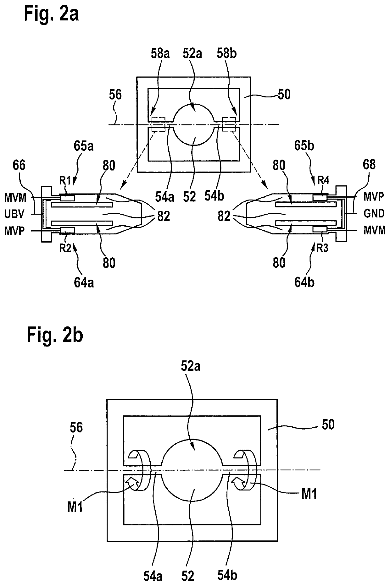
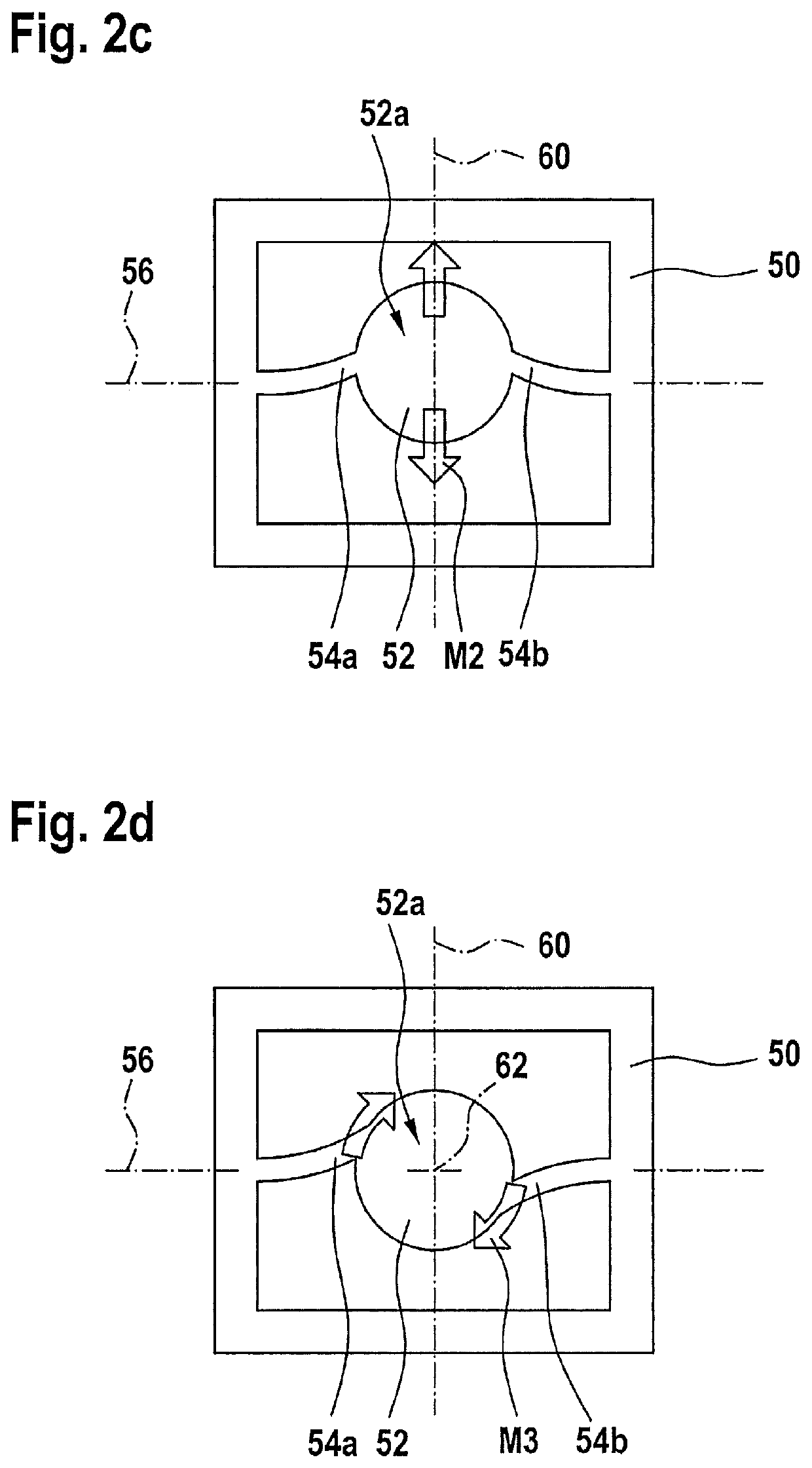
[0021]FIGS. 2a through 2i show schematic illustrations and coordinate systems for explaining a first specific embodiment of the mechanical component.

[0022]The mechanical component schematically illustrated in FIG. 2a has a mounting 50 and a movable part 52, movable part 52 being connected to mounting 50 via at least one first spring 54a and one second spring 54b. Springs 54a and 54b, which are also illustrated in part in enlarged scale in FIG. 2a, connect movable part 52 to mounting 50 in such a way that movable part 52 is movable with respect to mounting 50 at least about a rotational axis 56. Rotational axis 56 extends through a first anchoring area 58a of first spring 54a at mounting 50 and a second anchoring area 58b of second spring 54b at mounting 50. These anchoring areas 58a and 58b are illustrated in enlarged scale in FIG. 2a.

[0023]In the specific embodiment in FIGS. 2a through 2i, movable part 52 has at least one optically active surface 52a such as a reflective surface. ...


PUM

PropertyMeasurementUnit
frequenciesaaaaaaaaaa
anchoring areaaaaaaaaaaa
mechanicalaaaaaaaaaa

Abstract

A mechanical component has: a mounting; a movable part which, with the aid of at least one first spring and one second spring, is connected to the mounting in such a way that the movable part is movable about a rotational axis extending through a first anchoring area of the first spring on the mounting and a second anchoring area of the second spring on the mounting; a first sensor device with at least one first resistor which is situated on and / or in the first spring; and a second sensor device with at least one second resistor situated on and / or in the second spring. The first sensor device includes a first Wheatstone half bridge and the second sensor device includes a second Wheatstone half bridge. The first and second Wheatstone half bridges are connected to form a Wheatstone full bridge.

Description

BACKGROUND OF THE INVENTION1. Field of the Invention[0001]The present invention relates to a mechanical component and a manufacturing method for a mechanical component.2. Description of the Related Art[0002]FIG. 1 shows a schematic illustration of a conventional mechanical component.[0003]The conventional mechanical component schematically depicted in FIG. 1 has a movable part 10 which is connected to a mounting 14 via a first spring 12a and a second spring 12b. At its end connected to mounting 14, first spring 12a has a connecting structure 16 as described in published German patent application document DE 10 2010 029 074 A1, for example. Second spring 12b is provided without a connecting structure 16 of this type.[0004]Provided on connecting structure 16 is a Wheatstone full bridge 18, whose four resistors R1 through R4 are embedded on and / or in first spring 12a. Wheatstone full bridge 18 is grounded at a first contact 20, and is connected to a supply voltage at a second contact 2...

Claims


Application Information

Patent Timeline
Patent Type & Authority Patents(United States)
IPC IPC(8): G01R29/26G01R3/00B81B7/00G02B26/08
CPCG02B26/0858B81B7/008Y10T29/49002B81B2203/058B81B2203/056B81B2203/0109
Inventor HEINZELMANN, WOLFGANGIYAD AL DIBS, MOHAMADSTRAUB, RAINERPINTER, STEFANNJIKAM NJIMONZIE, FREDERICMUCHOW, JOERGGRUTZECK, HELMUTARMBRUSTER, SIMONREISS, SEBASTIAN
Owner ROBERT BOSCH GMBH
Why Eureka
Try Eureka