
MR data acquisition using physiological monitoring

a physiological monitoring and data acquisition technology, applied in the field of physiological monitoring, can solve the problems of ignoring the capability, affecting the patient's recovery period, blurring and ghosting of images, etc., and achieve the effect of prolonging the recovery period, reducing the resolution, and improving the quality of images

Active Publication Date: 2020-03-17
KONINK PHILIPS ELECTRONICS NV
View PDF21 Cites 1 Cited by
  • Summary
  • Abstract
  • Description
  • Claims
  • Application Information

AI Technical Summary

Benefits of technology

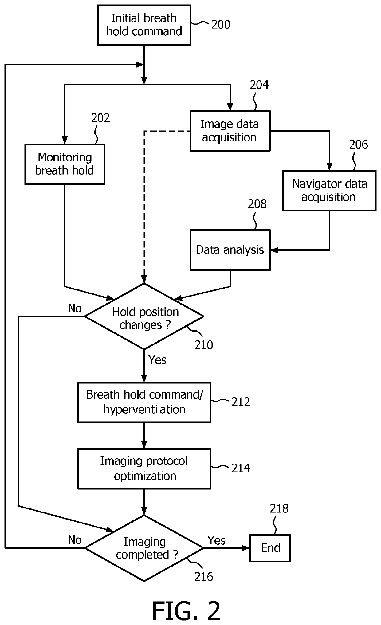
[0014]Embodiments of the invention have the advantage that with respect to the physiological situation of the patient the patient can dynamically be instructed to optimize behavior such that a respective MR imaging scan can be performed in an optimized manner, i.e. without motion-related problems like blurring and ghosting in the reconstructed MR image.
[0041]It has to be noted that in case the motion control detects that a patient cannot follow the breath hold instructions and also cannot hold the breath for a specified time not fulfilling a specified breath capability criteria, the imaging protocols can be set up to be automatically changed within the exam to a specified free breathing or a short breath hold protocol with a lower quality (lower resolution, 2D etc). The consequence is that the ‘recovery’ period of the patient is extended.

Problems solved by technology

In case of for example abdominal imaging this becomes a serious problem since physically necessary patient breathing and thus patient movement translates into blurring and ghosting of the acquired MR image.
Breath hold sequences typically are started too early when the breath hold state has not been reached yet which translates into blurring and ghosting of the image.
In the breath hold state, the breath hold may “drift away” also leading to motion related problems.
Also automated breath hold commands are not patient dependent thus neglecting the capability to follow the breath hold commands and to address the overall patient situation.

Method used


Image

  • MR data acquisition using physiological monitoring
  • MR data acquisition using physiological monitoring

Examples


Embodiment Construction

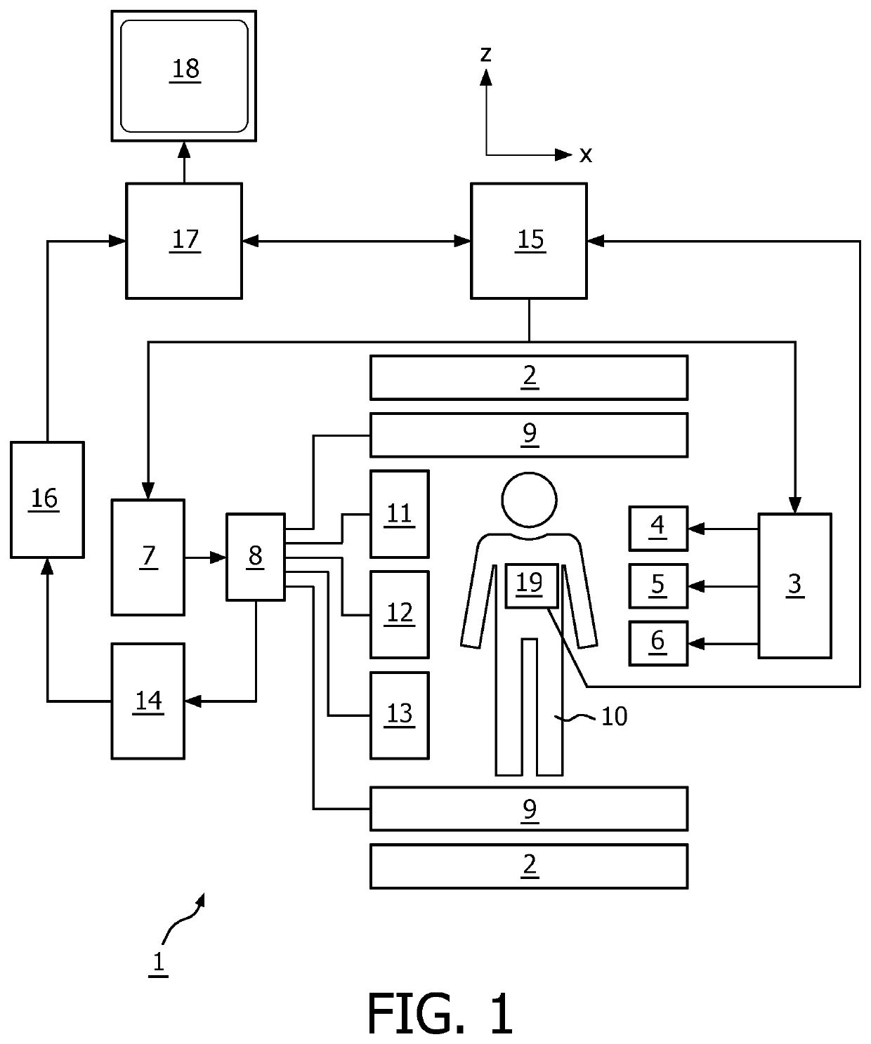
[0047]With reference to FIG. 1, an MR imaging system 1 is shown. The system comprises superconducting or resistive main magnet coils 2 such that a substantially uniform, temporarily constant main magnetic field B0 is created along a z-axis through an examination volume.

[0048]The magnetic resonance system applies a series of RF pulses and switched magnetic field gradients to invert or excite nuclear magnetic spins, induce magnetic resonance, refocus magnetic resonance, manipulate magnetic resonance, spatially or otherwise encode the magnetic resonance, saturate spins and the like to perform MR imaging.

[0049]More specifically, a gradient pulse amplifier 3 applies current pulses to selected ones of whole body gradient coils 4, 5 and 6 along x, y and z-axes of the examination volume. An RF transmitter 7 transmits RF pulses or pulse packets, via a send / receive switch 8 to an RF antenna 9 to transmit RF pulses into the examination volume. A typical MR imaging sequence is composed of a pac...


PUM


Abstract

Systems, devices and methods for performing a magnetic resonance imaging scan of a patient. For example, a method of performing a magnetic resonance imaging scan on a patient can include monitoring a physiological signal level of the patient, analyzing the monitored physiological signal level, and providing instructions to the patient and / or changing the environmental conditions exposed to the patient. The instructions and / or the change of the environmental conditions of the patient can be based on the monitored physiological signal level. The instructions can include an acoustic command and / or a visual command. The changing of the environmental conditions can include visual simulation, acoustic stimulation and / or air conditioning change.

Description

[0001]This application is a national stage application under U.S.C. § 371 of International Application No. PCT / IB2011 / 054501 filed on Oct. 12, 2011 and published in the English language on Apr. 19, 2012 as International Publication No. WO 2012 / 049634A1, which claims priority to European Application No. 101875169.9 filed on Oct. 14, 2010 , the entire disclosures of which are incorporated herein by reference.FIELD OF THE INVENTION[0002]The invention relates to a method of performing magnetic resonance imaging scan of a patient, a computer program product and an MRI system.BACKGROUND OF THE INVENTION[0003]Image-forming MR methods, which utilize the interaction between magnetic field and nuclear spins in order to form two-dimensional or three-dimensional images are widely used nowadays, notably in the field of medical diagnostics, because for the imaging of soft tissue they are superior to other imaging methods in many respects, they do not require ionizing radiation, and they are usual...

Claims


Application Information

Patent Timeline
Patent Type & Authority Patents(United States)
IPC IPC(8): A61B5/00G01R33/567A61B5/055G01R33/563
CPCA61B5/7285A61B5/055G01R33/5676A61B5/0037G01R33/5673G01R33/56366G01R33/56325
Inventor BECK, GABRIELLE MARIANNE
Owner KONINK PHILIPS ELECTRONICS NV
Learn More