Collet with ball-actuated expandable seal and/or pressure augmented radially expandable splines

a technology of expandable seals and collets, which is applied in the field of downhole tools, can solve the problems that the second key cannot fit in the profile of the first key, and achieve the effects of reducing the overall outer diameter, facilitating downhole passage, and less interferen

Active Publication Date: 2020-03-10
SC ASSET CORP
View PDF27 Cites 4 Cited by
  • Summary
  • Abstract
  • Description
  • Claims
  • Application Information

AI Technical Summary

Benefits of technology

[0028]Advantageously, therefore, where the collet is configured in the manner to permit radial growth as aforesaid, such advantageously permits the collet to be reduced in overall outer diameter. Such reduced diameter, not only in the region of the ball seat but also in the collet profile region, thereby permits the collet and the profile-region thereof to more easily pass downhole with less interference with various sliding sleeves which are not desired to be actuated, thereby reducing frictional wear on the profiled region of the collet and the integrity of collet profiles and thereby better ensuring when the collet reaches the desired sliding sleeve desired to be actuated that respective profile thereon is then able to sufficiently and reliably engage while simultaneously creating a seal to allow pressure to build on the uphole side of the ball, to then cause shear pins retaining the sliding sleeve in place to shear and then allow sliding sleeve to move downhole to thereby open a desired downhole port.

Problems solved by technology

However, an issue in cascading a plurality of ball-actuated sliding valves for fracking is that the bore of a downhole sliding valve has to be smaller than that of the sliding valves uphole thereof to allow a smaller-size ball to pass through those uphole sliding valves to reach the target downhole sliding valve.
However, the second key cannot fit in the profile of the first key.

Method used


Image

  • Collet with ball-actuated expandable seal and/or pressure augmented radially expandable splines
  • Collet with ball-actuated expandable seal and/or pressure augmented radially expandable splines
  • Collet with ball-actuated expandable seal and/or pressure augmented radially expandable splines

Examples


example ‘ a ’

EXAMPLE ‘A’

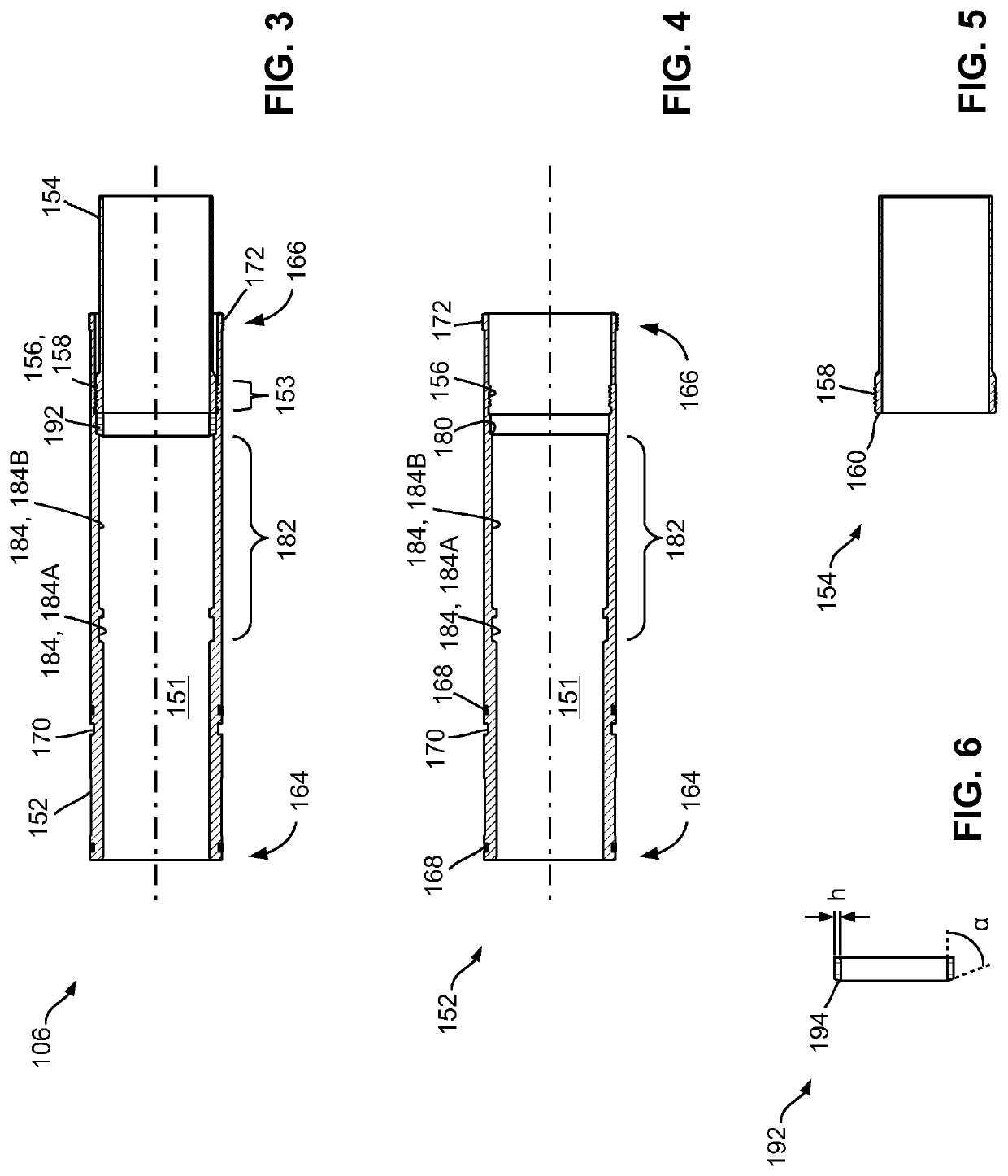
[0163]As noted above, FIG. 18 shows an example of a collet 200 of the present invention slidably received sliding sleeve 106. Collet 200 is configured to possess a radially expandable portion 206″ thereof, in the region of ball seat 214.

[0164]Specifically, in this example, collet 200, in the region of ball seat 214, is formed of API NP 80 steel, having a modulus of elasticity of 29,000,000 and a Poisson's Ratio of 0.29. The slidable sleeve 106 was also formed of API Grade N80 steel.

[0165]In this chosen example, collet 200 was provided with an initial radial clearance at the interface between the outer radial periphery of the collet 200 in the region of the ball seat 214 and the interior bore 151 of sleeve body 152 of 0.002 to 0.007 inches which was determined by applying material tolerances of the collet 200, namely the difference between the maximum and minimum dimensional tolerances between the collet 200 OD and the sliding sleeve 106 interior bore 151 internal diameter...


PUM


Abstract

A sliding valve has a valve body, a sliding sleeve received in a longitudinal bore of the valve body, and a collet receivable in a longitudinal bore of the sliding sleeve. The valve body has one or more fluid ports on an uphole portion of the sidewall thereof. The sliding sleeve is movable between an uphole closed position closing the one or more fluid ports and a downhole open position opening the one or more fluid ports. The collet comprises a metal portion about an uphole end of the collet, and a ball seat having a ball-seat surface radially inwardly sloped from uphole to downhole at an acute slope angle with respect to a longitudinal axis of the collet. The metal portion is radially outwardly expandable under a radially outward pressure to form a metal-to-metal seal at the interface between the collet and the sliding sleeve when the collet is received in the sliding sleeve.

Description

FIELD OF THE INVENTION[0001]The present disclosure relates generally to a downhole tool for use in fracking operations, and in particular to flowable collets for actuating sliding valves so as to open selected ports in a production string.BACKGROUND[0002]Downhole tools have been widely used in oil and gas industries. Many downhole tools comprise pressure-actuatable valves. For example, a prior-art ball-actuated sliding valve comprises a tubular valve housing having a bore and receiving in the bore a sliding sleeve. The sliding sleeve comprises a ball seat at an uphole end thereof, and is initially configured to an uphole closed position blocking one or more fluid ports on the sidewall of the valve housing. To actuate the sliding valve, a ball is dropped and seats against the ball seat of the sliding sleeve. Then, a fluid pressure is applied to the ball to actuate the sliding sleeve downhole to an open position to open the fluid ports on the valve housing.[0003]One or more ball-actua...

Claims


Application Information

Patent Timeline
Patent Type & Authority Patents(United States)
IPC IPC(8): E21B34/10E21B34/06E21B34/14E21B43/26E21B34/00
CPCE21B34/10E21B34/14E21B34/063E21B2034/007E21B43/26E21B2200/06E21B34/142
Inventor CAMPBELL, SEAN P.
Owner SC ASSET CORP
Why Eureka
Try Eureka