
Remotely controlled VTOL aircraft

Active Publication Date: 2020-02-18
BIRDSEYEVIEW AEROBOTICS LLC
View PDF69 Cites 12 Cited by
  • Summary
  • Abstract
  • Description
  • Claims
  • Application Information

AI Technical Summary

Benefits of technology

The patent describes a method for smoothly transitioning between different flight modes in an aircraft. The control system uses weighting factors to determine which controls to prioritize during the transition. This results in a more efficient and effective airplan during the transition between different flight modes.

Problems solved by technology

From a controls perspective, the transition process is extremely challenging.
Standard hover and forward flight control systems are inadequate to control the aircraft during the transition.
This task is difficult even for experienced pilots as evidenced by the fact that almost half of all Harriers manufactured have since been crashed.
However, the Osprey still has a mechanically sophisticated swash plate actuation system in each rotor which is expensive and difficult to maintain.
Modeling an aircraft at the needed level of fidelity is cost prohibitive outside of budgets scaled for national defense.

Method used


Image

  • Remotely controlled VTOL aircraft
  • Remotely controlled VTOL aircraft
  • Remotely controlled VTOL aircraft

Examples


Embodiment Construction

[0042]Aside from the preferred embodiment or embodiments disclosed below, this invention is capable of other embodiments and of being practiced or being carried out in various ways. Thus, it is to be understood that the invention is not limited in its application to the details of construction and the arrangements of components set forth in the following description or illustrated in the drawings. If only one embodiment is described herein, the claims hereof are not to be limited to that embodiment. Moreover, the claims hereof are not to be read restrictively unless there is clear and convincing evidence manifesting a certain exclusion, restriction, or disclaimer.

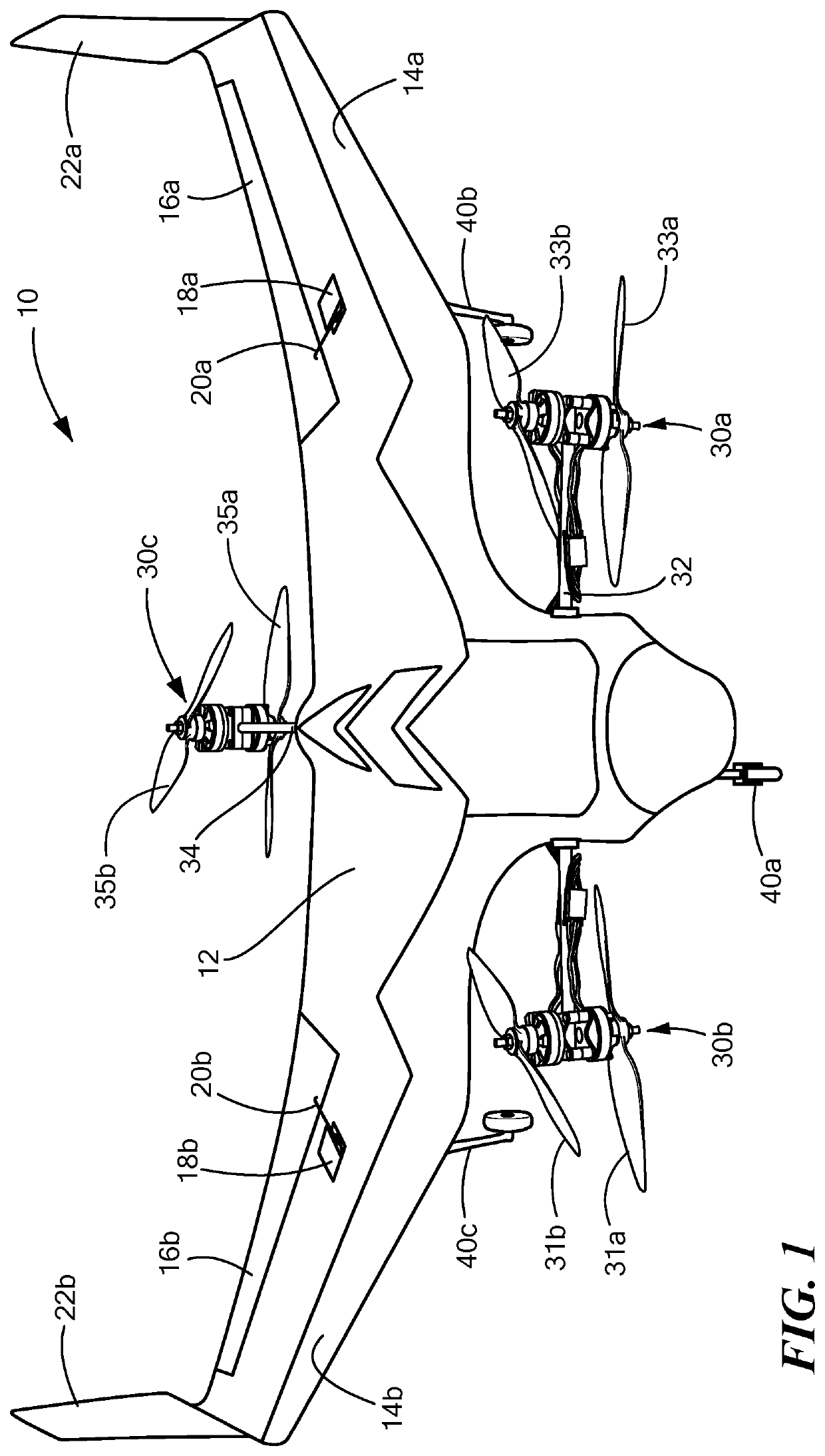
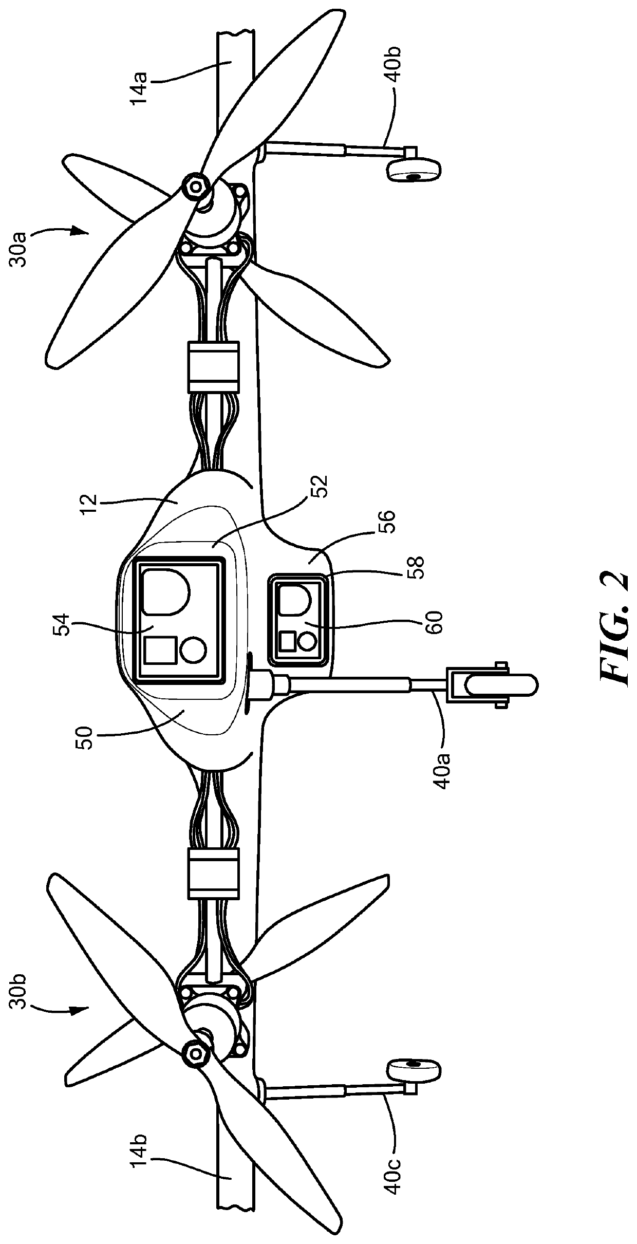
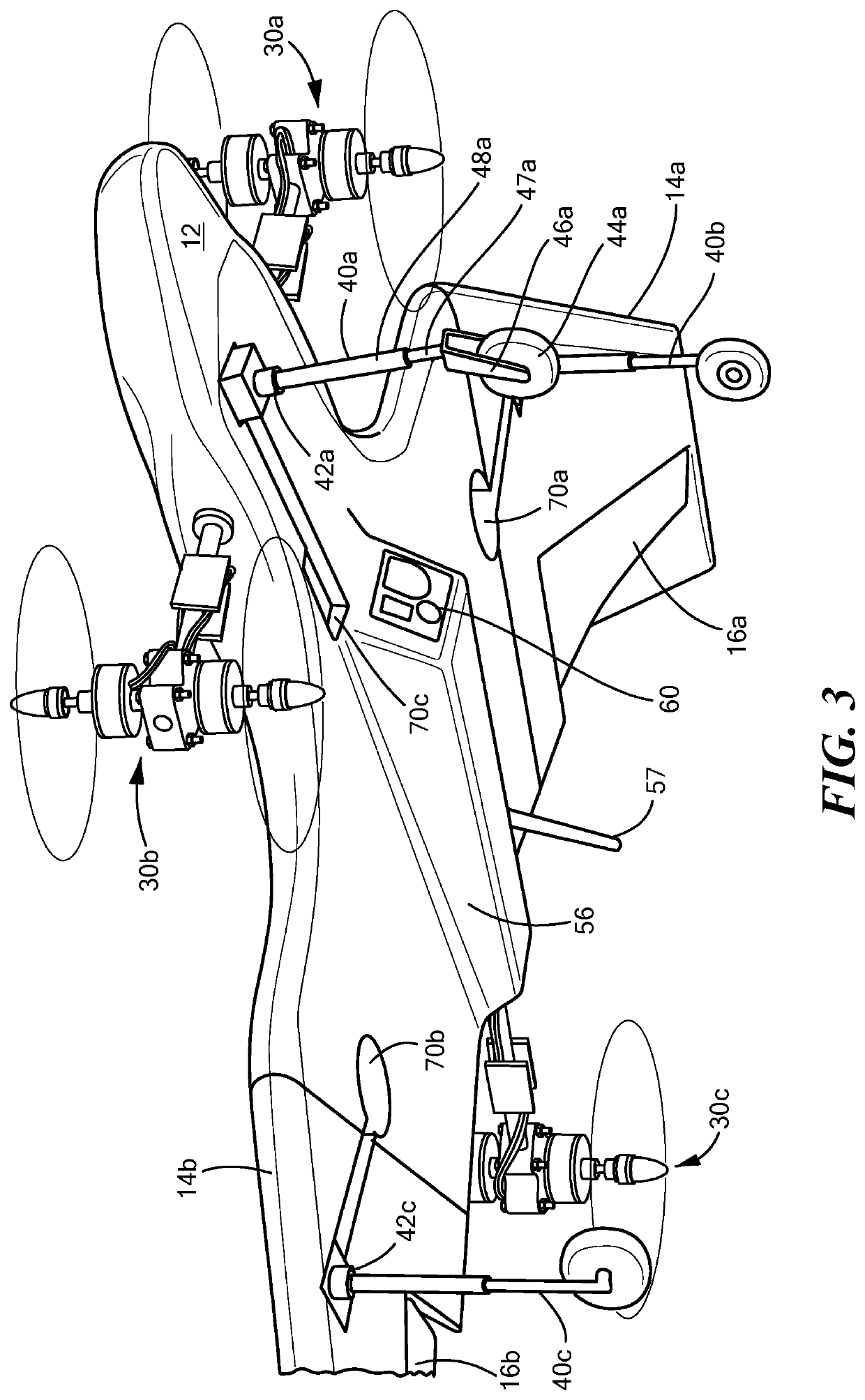
[0043]In one preferred embodiment, UAV 10, FIG. 1 includes fuselage or body 12, left wing 14a, and right wing 14b. Wings 14 may each include an elevon 16a, 16b each controlled by a respective elevon servo motor 18a, 18b connected to the elevon by a linkage 20a, 20b. Each wing may include a vertical tail section 22a, 22b. Fo...


PUM


Abstract

A remotely controlled VTOL aircraft includes an autopilot subsystem outputting helicopter control signals, and an autopilot subsystem outputting fixed wing control signals. A transition control subsystem is configured to receive said helicopter control signals, said fixed wing control signals, and a transition control signal. Control signals to be applied to the VTOL aircraft controls are calculated as a function of the transition percentage and weighting factors applied to the helicopter control signals and said fixed wing control signals.

Description

RELATED APPLICATIONS[0001]This application claims benefit of and priority to U.S. Provisional Application Ser. No. 62 / 410,995 filed Oct. 21, 2016, under 35 U.S.C. §§ 119, 120, 363, 365, and 37 C.F.R. § 1.55 and § 1.78, which is incorporated herein by this reference.FIELD OF THE INVENTION[0002]The present disclosure is in the technical field of unmanned aerial vehicles.BACKGROUND OF THE INVENTION[0003]Conventional unmanned aerial vehicles are typically either configured as fixed wing airplanes or rotary wing helicopters. Fixed wing airplanes excel at flight endurance, range, and speed but are limited by the large amount of space that is required for takeoff and landing and must always continue forward, often at significant speeds, thus limiting their ability to maneuver through tight spaces. Conversely, rotary wing helicopters excel at minimizing required takeoff and landing space and can stop in a midair hover and are thus more maneuverable than fixed wing airplanes but have limited...

Claims


Application Information

Patent Timeline
IPC IPC(8): B64C39/02B64C13/18B64C13/20B64C3/38B64D31/06G05D1/00B64C25/10B64C29/00
CPCB64C39/024B64C13/18B64C3/38B64C25/10B64C13/20B64C29/0033G05D1/0011B64D31/06B64C2201/146B64C2201/021B64C2211/00B64C2201/108B64C2201/102B64C2201/027B64C25/12G05D1/0858B64U10/25B64U2201/10B64U50/19B64U30/14B64U50/30B64U10/20B64U10/13B64U30/12B64U30/20B64U2201/20
Inventor SLOAN, ADAM RILEYMILLER, NATHANIEL
Owner BIRDSEYEVIEW AEROBOTICS LLC
Learn More