Vibratory pile-driving device

a technology of vibrating piles and driving devices, which is applied in the direction of bulkheads/piles, soil preservation, construction, etc., can solve the problems of particularly undesirable noise radiation, and achieve the effects of high flexibility, high flexibility, and reliable follow-up of vibrating movements

Active Publication Date: 2020-02-11
BAUER MASCH GMBH
View PDF23 Cites 0 Cited by
  • Summary
  • Abstract
  • Description
  • Claims
  • Application Information

AI Technical Summary

Benefits of technology

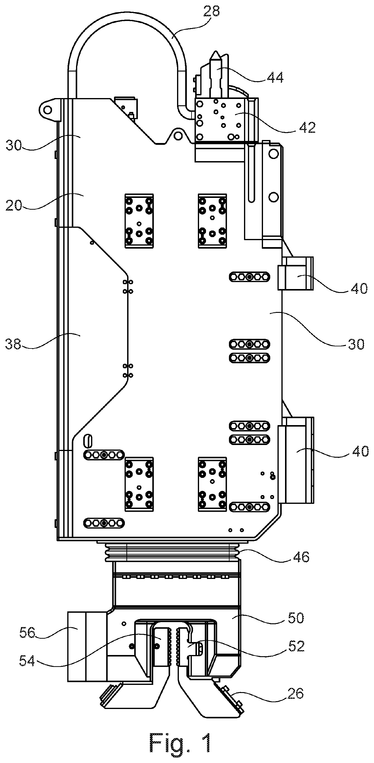
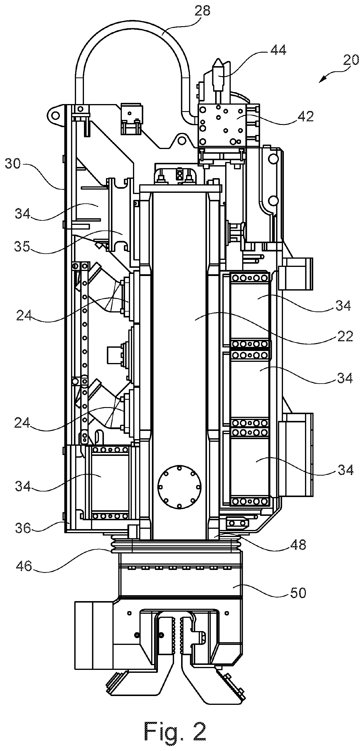
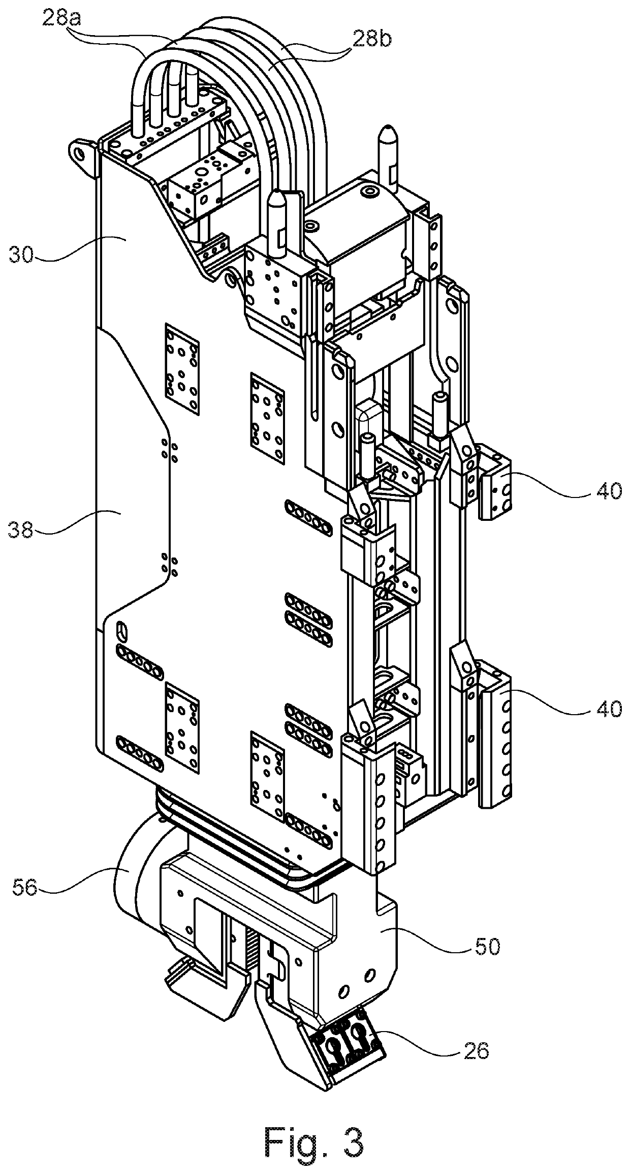
[0017]According to an embodiment variant of the vibratory apparatus according to the invention it is of advantage that on an underside of the transmission housing a holding unit for clamping and holding a driving material is mounted and that the soundproof housing is spaced from the holding unit through the formation of an annular gap that is covered by an elastic cover element. The holding unit is a clamping collet in particular which is designed for clamping and for transmitting vibrations to a sheet pile or another driving material to be driven in. This holding unit is not in direct contact with the soundproof housing. In fact, the holding unit is spaced from the soundproof housing by an annular gap. This gap is covered by an elastic cover element so that no direct sound radiation can arise from this gap.
[0018]In this connection it is especially preferred that the cover element is designed as a bellows which is fixed on the one hand on the soundproof housing and on the other hand on the holding unit. The bellows shows a certain flexibility, allowing it to reliably follow the vibratory movements of the holding unit.
[0019]Another preferred embodiment of the invention resides in the fact that in an upper area of the soundproof housing a quick-coupling unit for the oil discharge line and the oil supply line is arranged. Hence, despite the external oil cooling there is the possibility of easily uncoupling the vibration generator from the carrier implement and the mast for maintenance purposes. The quick-coupling unit has corresponding coupling plugs that close the oil lines in a leak-free manner when the coupling unit is released. The corresponding coupling counterparts of the quick-coupling unit are arranged on a feed carriage that is supported in a movable manner along the mast. Thus, despite the external cooling a high flexibility is still reached during maintenance works without running the risk of environmental pollution.
[0020]According to an embodiment variant of the invention a further reduction of sound radiation is achieved in that on the external side of the soundproof housing at least one connecting means with a support surface is provided, on which a damping covering is arranged. The damping covering can be a rubber element or another cellular foam or plastic element. The connecting means preferably serves as a support for a catch of a driving material safety chain on the clamping collet. The driving material safety chain reliably prevents an accidental dropping of a sheet pile from the holding unit. The connecting means can be provided with a quick-release connecting element, such as screw or hook closures, or form part of the quick-release coupling unit.

Problems solved by technology

Such a noise radiation is particularly undesirable in the case of works taking place in an inner city area.

Method used


Image

  • Vibratory pile-driving device
  • Vibratory pile-driving device
  • Vibratory pile-driving device

Examples


Embodiment Construction

[0027]According to FIG. 5 a vibratory pile-driving apparatus 10 pursuant to the invention has a carrier implement 12 which comprises in a known manner a crawler-track running gear as an undercarriage and an upper carriage arranged thereon in a rotatable manner. On the upper carriage of the carrier implement 12 a mast 14 is linked in a pivotable manner which is designed as a leader with a lower mast part 15, along which an upper mast part 16 is guided in a vertically movable manner. Along a front side of the upper mast part 16 a linear guide 17 is designed, along which a vibration generator 20 according to the invention is guided by a guiding means 40.

[0028]On its upper side the vibration generator 20 is releasably coupled via a quick-coupling 41 to a feed carriage 18 that can be moved via a feed means along the linear guide 17 of the upper mast part 16. To form the quick-coupling 41 a lower quick-coupling unit 42 is arranged on the vibration generator 20, which establishes a connect...


PUM

PropertyMeasurementUnit
areaaaaaaaaaaa
forceaaaaaaaaaa
frictionaaaaaaaaaa

Abstract

The invention relates to a vibratory pile-driving apparatus having a carrier implement with a mast, on which, for the purpose of generating vibrations, a vibration generator with a transmission housing is supported, in which at least one pair of rotatably supported unbalanced units is arranged that are driven in a rotating manner by at least one rotary drive. According to the invention provision is made in that the transmission housing is surrounded by a soundproof housing, in which the transmission housing is supported by way of damping elements, and in that from the transmission housing at least one oil supply line and one oil discharge line are led out of the soundproof housing, wherein transmission oil can be cooled outside the soundproof housing.

Description

BACKGROUND OF THE INVENTION[0001]The invention relates to a vibratory pile-driving apparatus having a carrier implement with a mast, on which, for the purpose of generating vibrations, a vibration generator with a transmission housing is supported, in which at least one pair of rotatably supported unbalanced units is arranged that are driven in a rotating manner by at least one rotary drive, in accordance with the detailed description hereinbelow.FIELD OF THE INVENTION[0002]Vibratory pile-driving apparatuses of such type are provided, in particular, for driving and extracting sheet piles into or out of the ground. As a result of the generated vibrations that are caused by unbalanced units driven in a rotating manner the ground is brought into a virtually liquid state so that a pile or beam can be pressed into the ground with relatively little force.BRIEF SUMMARY OF THE INVENTION[0003]The unbalanced units are driven in a rotating manner by one or several rotary drives using gear tran...

Claims


Application Information

Patent Timeline
Patent Type & Authority Patents(United States)
IPC IPC(8): E02D7/18B06B1/16E02D11/00E02D5/02
CPCE02D7/18B06B1/16E02D2300/0001E02D11/00E02D5/02E02D3/074
Inventor OTTO, HANS-PHILIPPKRAUS, WOLFGANGLINDERMAIR, BERNHARD
Owner BAUER MASCH GMBH
Why Eureka
Try Eureka