High-brightness luminescent-based lighting device

a luminescent-based, high-bright technology, applied in the direction of lighting and heating apparatus, semiconductor devices for light sources, instruments, etc., can solve the problems of reducing efficiency, increasing the temperature of the converter, and affecting the coherence and eye safety, so as to achieve the effect of easy tuning

Active Publication Date: 2020-01-21
SIGNIFY HLDG BV
View PDF5 Cites 0 Cited by
  • Summary
  • Abstract
  • Description
  • Claims
  • Application Information

AI Technical Summary

Benefits of technology

[0005]For various applications such as projection, stage lighting and automotive headlamps, it is desirable to have high intensity light sources. Such light sources can be based on laser light or luminescent concentrator based concepts. However, in the case of using lasers, coherence and eye safety is an issue. For that reason it is desirable to convert the laser light to other wavelengths and / or to light with less coherence with a converter. However, during the conversion large amount of heat may be produced in a small volume which leads to a temperature rise of the converter. In the same way luminescent concentrator based light sources need to be cooled effectively in order to avoid thermal quenching. As a result of cooling surfaces the efficiency is reduced considerably.
[0008]Especially, the excitation and / or emission spectral bands have full width half maximum (FWHM) of especially at maximum 80 nm, even more especially at maximum 60 nm, and yet even more especially at maximum 30 nm, such as at maximum 20 nm, like at maximum 5 nm. Especially such narrow bands appear to be most efficient in the present lighting device wherein excitation may be done at a wavelength close to the emission wavelength. Especially, the difference in excitation wavelength and peak maximum of the emission band is equal to or below about 80 nm, such as at maximum 60 nm, more especially equal to or below about 50 nm, even more especially at maximum 30 nm, such as especially not more than about 20 nm. However, in a specific embodiment, the difference in excitation wavelength and peak maximum of the emission band may be at least 5 nm. In this way, the Stokes-shift related energy loss is relatively low. For instance, when exciting with UV radiation a luminescent material emitting in the visible, the Stokes-shift related energy loss is high (with the Stokes-shift related energy loss being higher for e.g. red light than for green light, and being higher for green light than for blue light).
[0015]With such a lighting device, a high intensity light source may be provided, without a high energy loss, and thus without potential thermal problems. Further, with such lighting device it is possible to safely use the high intensity coherent laser light (see also below) in an efficient way, while reducing the risks of the laser light, as the converted light (luminescent material light) is applied. Further, as a result of the relative low Stokes shift, less than about 13% of the energy is lost as a result of Stokes-shift related power loss (see also below). Hence, especially the difference in wavelength between the light source light maximum (i.e. peak) and the emission maximum (i.e. peak) is equal to or less than 80 nm. Especially, the solid state-based light source is configured to provide said light source light with especially 0<MM3−MX2≤60 nm, even more especially 0<MM3−MX2≤30 nm, such as being at least 5 nm (5 nm<MM3−MX2≤30 nm). Hence, the solid state-based light source and the luminescent material are selected such, that these conditions can be met. Alternatively, the solid state-based light source is configured to provide said light source light with especially 0<MM3−MX2≤2500 cm−1, especially 0<MM3−MX2≤2000 cm−1, even more especially 0<MM3−MX2≤1500 cm−1.
[0037]Most known quantum dots with emission in the visible range are based on cadmium selenide (CdSe) with shell such as cadmium sulfide (CdS) and zinc sulfide (ZnS). Cadmium free quantum dots such as indium phosphide (InP), and copper indium sulfide (CuInS2) and / or silver indium sulfide (AgInS2) can also be used. Quantum dots show very narrow emission band and thus they show saturated colors. Furthermore, the emission color can easily be tuned by adapting the size of the quantum dots.

Problems solved by technology

However, in the case of using lasers, coherence and eye safety is an issue.
However, during the conversion large amount of heat may be produced in a small volume which leads to a temperature rise of the converter.
As a result of cooling surfaces the efficiency is reduced considerably.

Method used


Image

  • High-brightness luminescent-based lighting device
  • High-brightness luminescent-based lighting device
  • High-brightness luminescent-based lighting device

Examples


Embodiment Construction

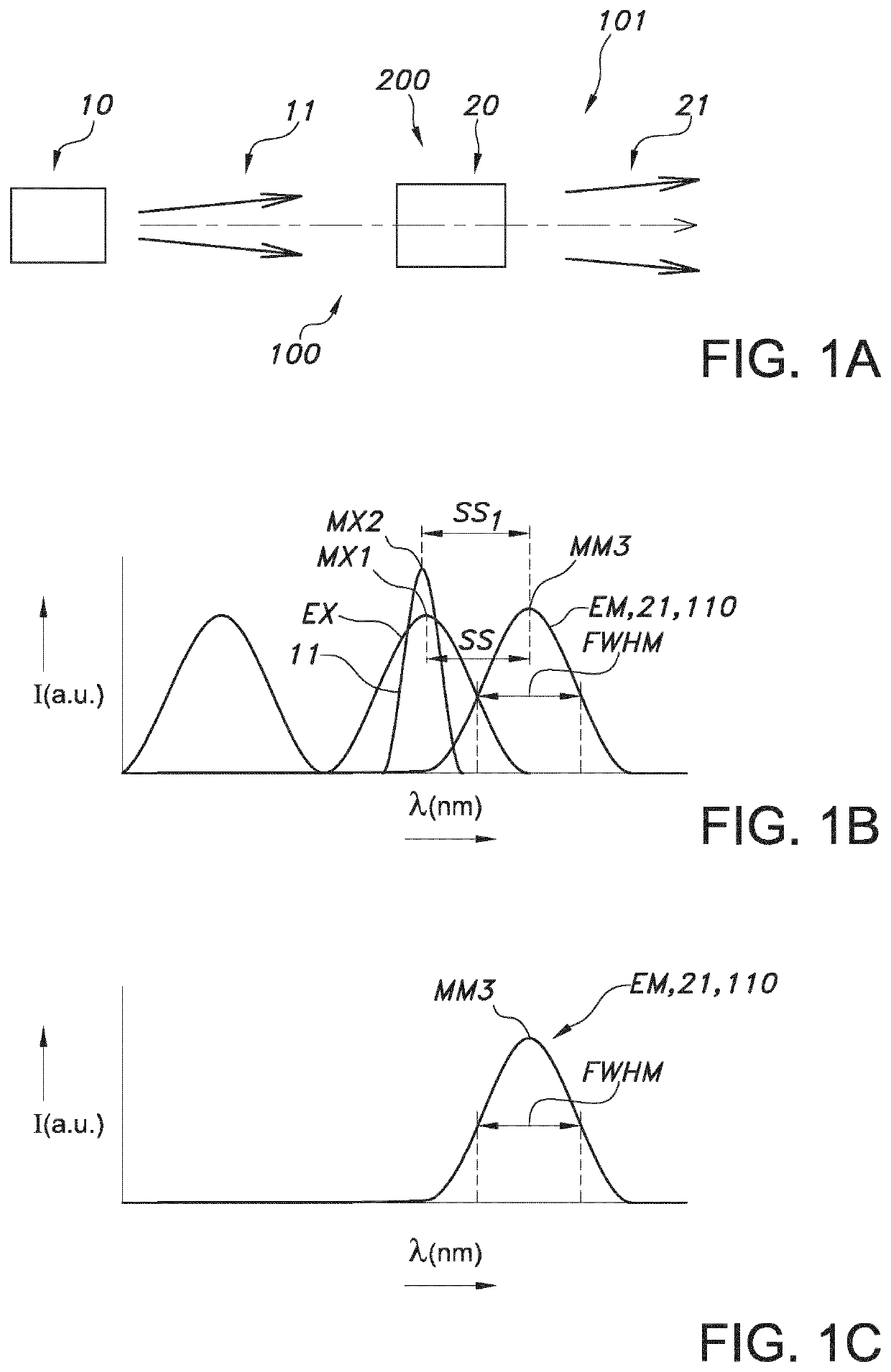
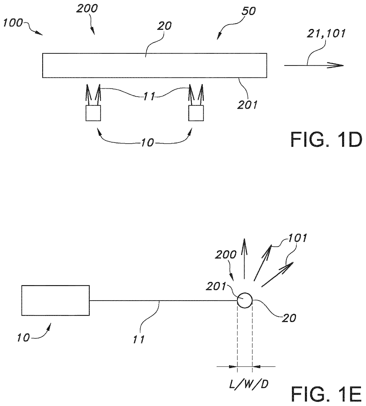
[0066]FIG. 1a schematically depicts an embodiment of a lighting device 100 configured to generate lighting device light 101. The lighting device 100 comprises a solid state-based light source 10, configured to generate light source light 11, and a luminescent material 20, configured to convert at least part of the light source light 11 into luminescent material light 21. The light downstream of the luminescent material 20 is indicated with reference 101. The light 101 at least comprises the emission or luminescence of the luminescent material 20, i.e. the luminescent material light 21. Optionally, some of the light source light 11 might also be comprised by the lighting device light 101. This may not be a problem, as the wavelength of the light source light and the luminescent material light may be substantially identical.

[0067]Especially, the lighting device light 101 substantially consists of the luminescent material light 21, such as 80% or more, such as at least 90% of the power...


PUM

PropertyMeasurementUnit
full width half maximumaaaaaaaaaa
wavelengthaaaaaaaaaa

Abstract

The invention provides a lighting device configured to generate lighting device light, wherein the lighting device light includes an emission band in the visible part of the spectrum which represents at least 80% of the total power (W) of the lighting device light in the visible part of the spectrum, wherein the emission band has a full width half maximum of at maximum 60 nm, and wherein the emission band has a peak maximum (MM3), wherein said emission band includes luminescent material light, wherein the lighting device includes (i) a solid state-based light source, configured to generate light source light having a peak maximum (MX2), and (ii) a luminescent material, configured to convert at least part of the light source light into said luminescent material light, wherein the solid state-based light source is configured to provide said light source light with 0<MM3−MX2<60 nm.

Description

CROSS-REFERENCE TO PRIOR APPLICATIONS[0001]This application is the U.S. National Phase application under 35 U.S.C. § 371 of International Application No. PCT / EP2016 / 056717, filed on Mar. 25, 2016, which claims the benefit of European Patent Application No. 15162576.1, filed on Apr. 7, 2015. These applications are hereby incorporated by reference herein.FIELD OF THE INVENTION[0002]The invention relates to a lighting device, especially for providing colored light. The invention further relates to a lighting apparatus, comprising such lighting device, and optionally further lighting devices, especially configured to provide white light.BACKGROUND OF THE INVENTION[0003]High intensity light sources are known in the art. U.S. Pat. No. 3,369,117, for instance, describes a miniature high intensity lamp comprising a base, an arm having one end pivotally mounted on said base, said arm comprising telescoping sections whereby the total length of said arm may be varied, a head pivotally connecte...

Claims


Application Information

Patent Timeline
Patent Type & Authority Patents(United States)
IPC IPC(8): F21V9/08F21V29/502F21V8/00B82Y20/00F21Y115/10F21Y115/30
CPCF21V29/502F21V9/08G02B6/0003F21Y2115/30B82Y20/00Y10S977/818Y10S977/95Y10S977/815Y10S977/814F21Y2115/10Y10S977/951Y10S977/774F21K9/64H01L33/502
Inventor VAN BOMMEL, TIESHIKMET, RIFAT ATA MUSTAFA
Owner SIGNIFY HLDG BV
Why Eureka
Try Eureka