HV-COB LED light source based on remote phosphor powder excitation

A technology of HV-COB LED and remote phosphor, which is applied in the direction of semiconductor devices, electrical components, circuits, etc., can solve the problems of small luminous flux of a single product, aging of LED chips, and lack of color rendering, so as to improve the light efficiency of products The effects of color rendering index, anti-aging, and improvement of light conversion efficiency

Inactive Publication Date: 2015-04-15
TIANSHUI HUATIAN TECH
View PDF10 Cites 1 Cited by
  • Summary
  • Abstract
  • Description
  • Claims
  • Application Information

AI Technical Summary

Problems solved by technology

The traditional blue light chip + fluorescent powder glue potting process, the red light component in the synthesized white light is so small that it cannot achieve high color rendering, and to achieve good color rendering will reduce the light efficiency to a certain extent At the same time, the cost will be greatly increased; and the light will be absorbed by the LED chip after being reflected by the phosphor powder, which will cause the LED chip to age; it will also cause common and difficult to solve defects such as glare and light spots.
Traditional LED packaging is mainly based on small and medium power single-chip packaging. The luminous flux of a single product is relatively small, and the overall luminous efficacy is not higher than 100lm / W when making lamps.

Method used


Image

  • HV-COB LED light source based on remote phosphor powder excitation
  • HV-COB LED light source based on remote phosphor powder excitation
  • HV-COB LED light source based on remote phosphor powder excitation

Examples


Embodiment Construction

[0014] The present invention will be described in detail below in conjunction with the accompanying drawings and specific embodiments.

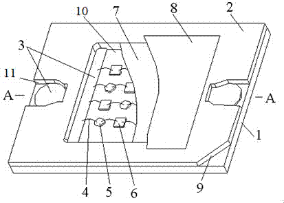
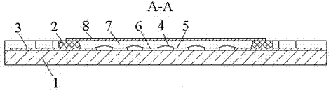
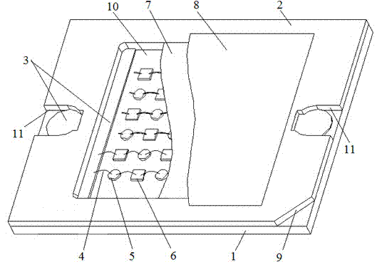
[0015] Such as figure 1 and figure 2 As shown, the first embodiment of the LED light source of the present invention includes a substrate 1, on which a square ring-shaped dam 2 made of COB dam glue is arranged, and a marking gap 9 is provided on the dam 2, and the middle part of the dam 2 It is a square bowl 10, and two gaps 11 are symmetrically arranged on the dam 2; two disconnected silver-plated pads 3 are arranged between the substrate 1 and the dam 2, and one end of the pad 3 extends into the bowl 10, the other end of the pad 3 is located outside the bowl 10, and a gap 11 exposes a part of the pad 3 outside the bowl 10; the substrate 1 in the bowl 10 is provided with four LED chip components in parallel, each The LED chip components are arranged along the connection direction of the two gaps 11, and all the LED chip components are loc...


PUM


Abstract

The invention relates to an HV-COB LED light source based on remote phosphor powder excitation. The HV-COB LED light source comprises a base plate and a remote phosphor powder excitation film, wherein a coffer dam with a square bowl in the middle part is arranged on the base plate, and two notches are symmetrically formed in the coffer dam; two bonding pads are arranged between the base plate and the coffer dam, and are exposed at the notches; a plurality of LED chip components connected with the two bonding pads are arranged in the bowl in parallel, and each LED chip component is formed by serially connecting high-voltage red light LED chips and high-voltage blue light LED chips at intervals, wherein the number of the high-voltage red light LED chips and the number of the high-voltage blue light LED chips are the same; the periphery of each high-voltage red light LED chip is adjacent to the high-voltage blue light LED chips respectively, and the periphery of each high-voltage blue light LED chip is adjacent to the high-voltage red light LED chips; the bowl is filled with a plastic packaging body. The light source adopts light-emitting wafers and phosphor powder which are separated, and remote white light excitation is realized, so that the quality of heat generated by phosphor powder excited homogeneous light is reduced, the temperatures of the chips are reduced, and the aging of the chips is relieved; the thermal quenching performance of the phosphor powder is avoided, the light failure is reduced, and the lighting effect is improved.

Description

technical field [0001] The invention belongs to the technical field of semiconductor lighting and relates to an LED light source, in particular to an HV-COB LED light source based on remote phosphor excitation. Background technique [0002] LED (Light-Emitting Diode, light-emitting diode) packaging technology is currently in a stage of rapid development. At this stage, there are various packaging forms of LED white light lighting products on the market, which have gradually replaced traditional first- and second-generation light sources such as incandescent lamps and fluorescent lamps. . [0003] At present, most of the solutions for LED packaging to achieve white light are blue LED chips (also called chips) + YAG yellow phosphor powder, that is, the phosphor powder is mixed in the packaging colloid, and the bubbles in the mixed colloid are removed by vacuum defoaming technology. On the surface of the light-emitting chip and solidified, the yellow phosphor powder is excited...

Claims


Application Information

Patent Timeline
Patent Type & Authority Applications(China)
IPC IPC(8): H01L25/075H01L33/48H01L33/50H01L33/54H01L33/64
CPCH01L2224/48091H01L2224/48137H01L2924/00014
Inventor 姚全林张弘慕蔚邵荣昌钱昱王江
Owner TIANSHUI HUATIAN TECH
Why Eureka
Try Eureka