Electric power steering apparatus
a technology of electric power steering and steering coil, which is applied in the direction of electric steering, control systems, vehicle components, etc., can solve the problems of steering angle sensor, coil damage or the like, not indispensable and not provided, etc., and achieve the effect of more precise temperature estimation
- Summary
- Abstract
- Description
- Claims
- Application Information
AI Technical Summary
Benefits of technology
Problems solved by technology
Method used
Image
Examples
first embodiment
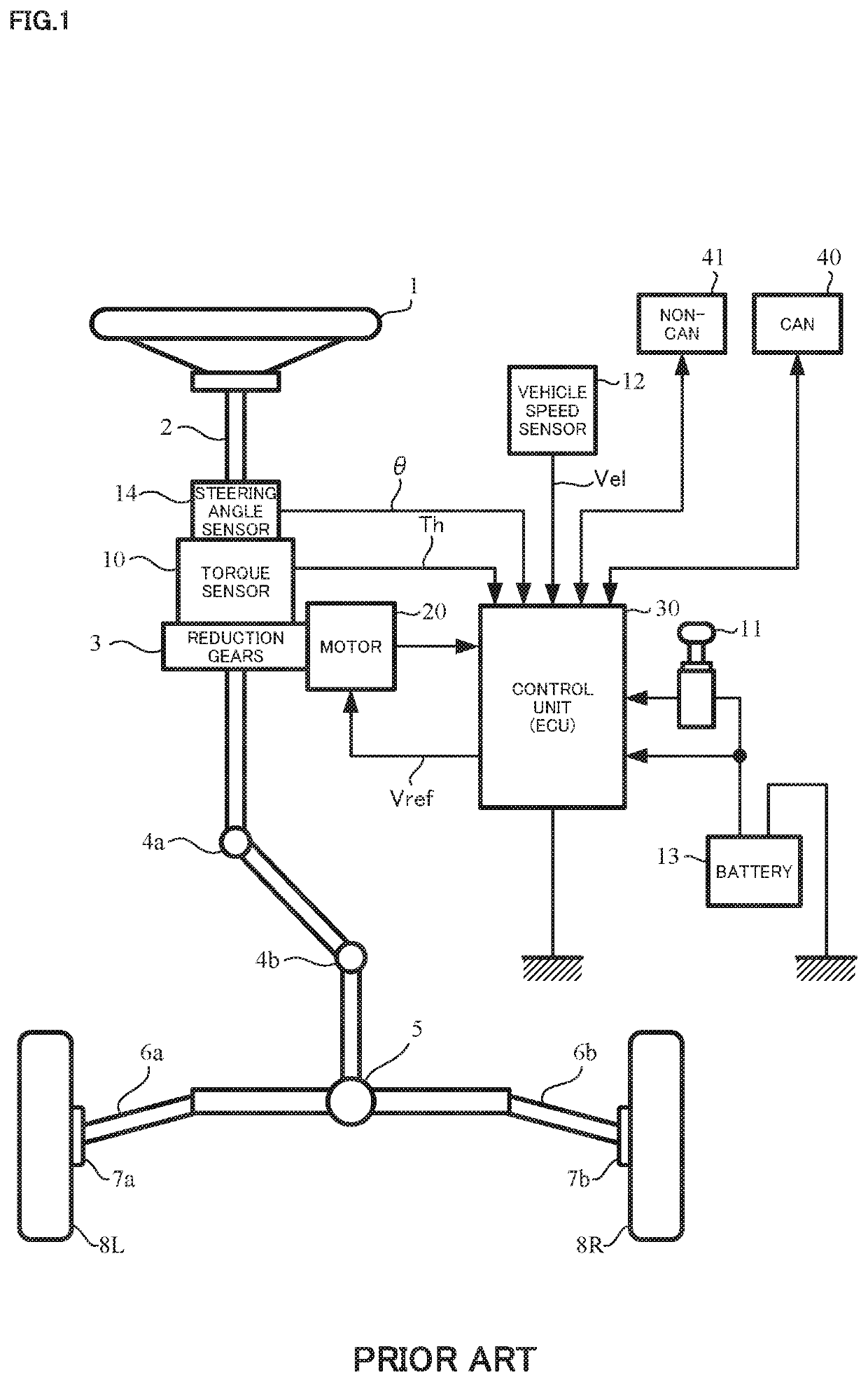
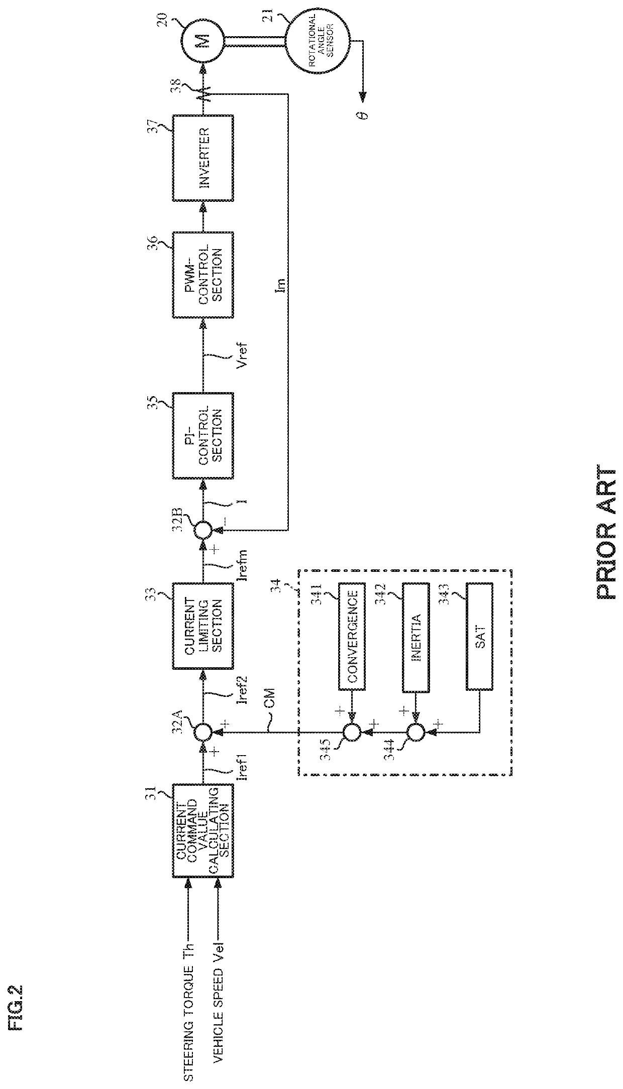
[0034]FIG. 4 shows a configuration example (a first embodiment) of the embodiment of the present invention corresponding to FIG. 2, the same configurations are designated with the same numerals, and the explanation is omitted.
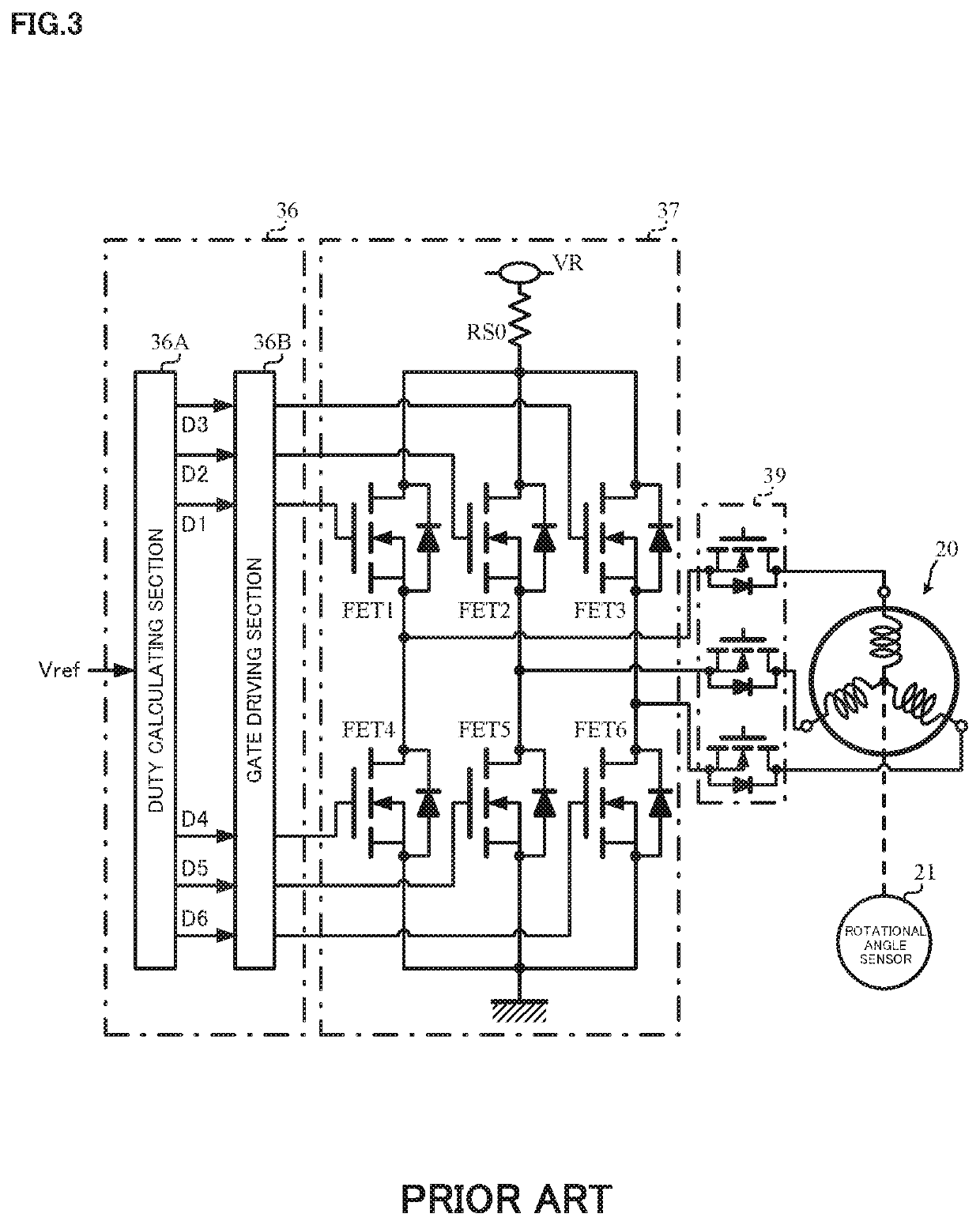
[0035]An electric power steering apparatus of the present embodiment drives and controls a three-phase (the U-phase, the V-phase and the W-phase) brushless motor, and an object for estimation of the coil temperature is a coil shown by the circle in FIG. 5. FIG. 5 is a sectional view which schematically shows a side obtained by cutting a configuration of a motor 20 with a virtual plane including a central axis Zr. The motor 20 comprises a rotational angle sensor (a resolver) 21, a housing 22, bearings 23 and 24, a rotor 50, and a stator 60. The resolver 21 comprises a resolver rotor 21a and a resolver stator 21b, and is supported by a terminal block 25. The housing 22 includes a cylindrical housing 22a and a front bracket 22b, and a bottom part 22c is formed at ...
second embodiment
[0057]the present invention will be described.
[0058]Though a whole configuration of the second embodiment is similar to one of the first embodiment, a configuration of the coil temperature calculating section is different.
[0059]The setting shown by the following expression 20 can be applied to the expressions 17 to 19 which the calculation at the coil temperature calculating section 350 of the first embodiment is based on because of symmetry of the phases.
GUU′=GVV′=GWW′=GL
GUV′=GVU′=GUW′=GWU′=GVW′=GWV′=GM
GEU′=GEV′=GEW′=GE
GTU=GTV=GTW=GTE [Expression 20]
The following expressions 21 to 23 are obtained by substituting the above expression 20 for the expressions 17 to 19, and arranging the substitution results.
TU=GLQU+GM(QV+QW)+GEQE+GTETE [Expression 21]
TV=GLQV+GM(QW+QU)+GEQE+GTETE [Expression 22]
TW=GLQW+GM(QU+QV)+GEQE+GTETE [Expression 23]
[0060]FIG. 9 expresses the above expressions 21 to 23 with a block diagram, and the coil temperature calculating section of the second embodimen...
third embodiment
[0063]the present invention will be described.
[0064]A configuration example of the third embodiment is shown in FIG. 10. Compared with the configuration example of the first embodiment shown in FIG. 4, the coil temperature calculating section 350 is replaced with a coil temperature calculating section 550, and the coil temperatures TU′, TV′ and TW′ retained in the memories 360, 370 and 380 are inputted into the coil temperature calculating section 550 in addition to the coil calorific values QU, QV and QW, the substrate calorific value QE and the substrate temperature TE. The coil temperature estimating section comprises the coil calorific value calculating sections 310, 320 and 330, the substrate calorific value calculating section 340 and the coil temperature calculating section 550.
[0065]The coil temperature calculating section 550 calculates the coil temperatures TU, TV and TW in respective phases on the basis of a differential equation of heat conduction.
[0066]The differential ...
PUM
 Abstract
Description
Claims
Application Information
 - R&D
- Intellectual Property
- Life Sciences
- Materials
- Tech Scout
- Unparalleled Data Quality
- Higher Quality Content
- 60% Fewer Hallucinations
Browse by: Latest US Patents, China's latest patents, Technical Efficacy Thesaurus, Application Domain, Technology Topic, Popular Technical Reports.
© 2025 PatSnap. All rights reserved.Legal|Privacy policy|Modern Slavery Act Transparency Statement|Sitemap|About US| Contact US: help@patsnap.com


