
Systems and methods for installing and stabilizing a pier

a technology of metal piers and systems, applied in the direction of lifting devices, protective foundations, constructions, etc., can solve the problems of difficulty in stabilizing a metal pier against lateral loads, metal piers have a tendency to deflect, bend or buckle, etc., to prevent or minimize vertical loads on the pier, reduce lateral displacement, prevent or minimize the effect of vertical displacemen

Active Publication Date: 2019-12-17
TELLA FIRMA
View PDF35 Cites 5 Cited by
  • Summary
  • Abstract
  • Description
  • Claims
  • Application Information

AI Technical Summary

Benefits of technology

The present invention is about a system and method that installs a stabilizing device to make metal piers or other structures more stable in unstable soil. The system prevents or minimizes vertical loads on the pier and reduces lateral displacement caused by loads on the pier. This is achieved by configuring the stabilizing device so that it can adapt to the soil conditions and transfer loads to the soil through the device instead of directly to the pier. In summary, the invention improves the stability of metal piers in unstable soil.

Problems solved by technology

Although suspending slab foundations on piers above the ground to create a protective void between the ground and the slab foundations works well, implementing it has its challenges.
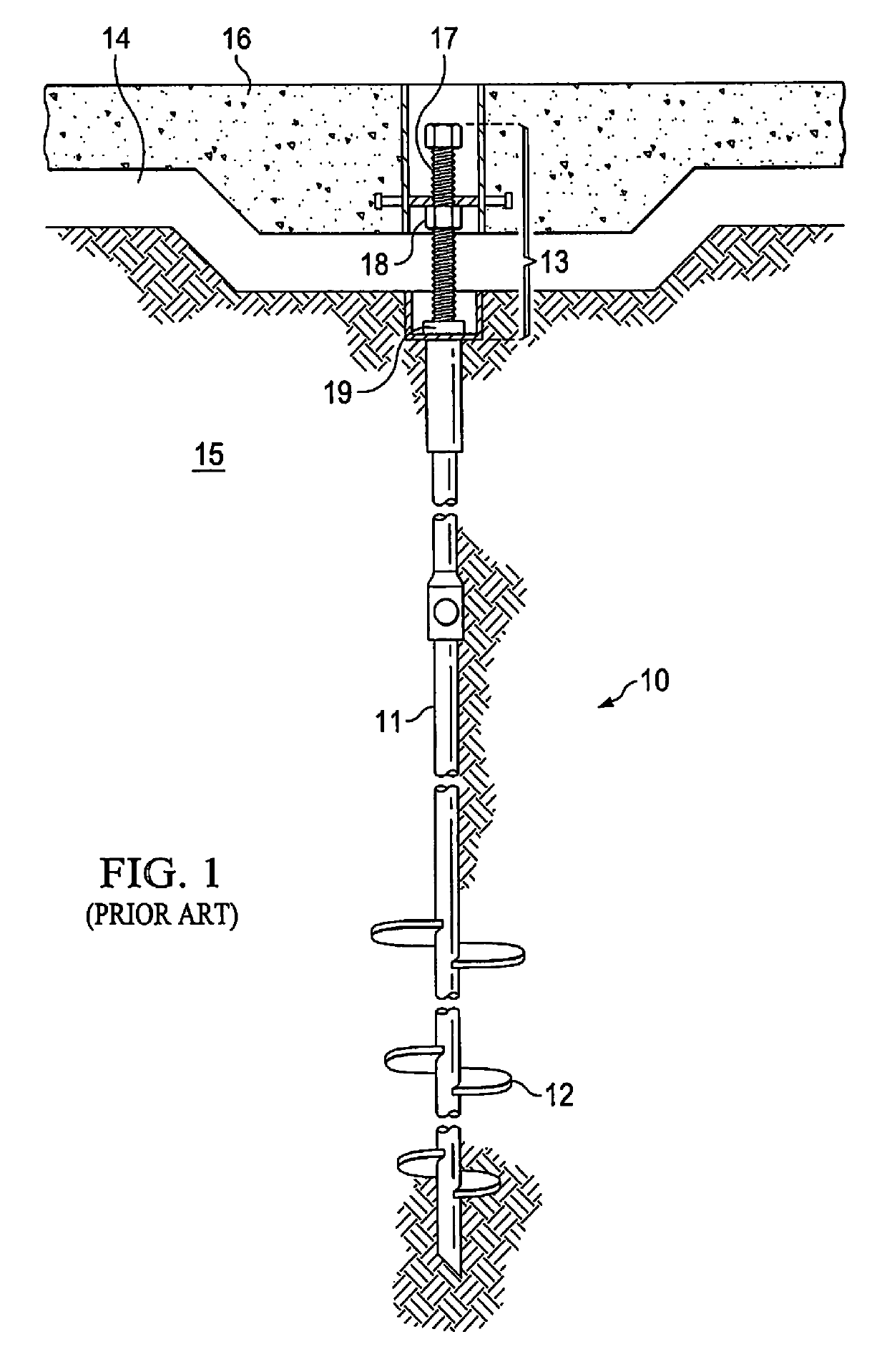
As noted above, there is difficulty in stabilizing a metal pier against lateral loads in unstable soil.
Metal piers have a tendency to deflect, bend or buckle when a lateral load is applied to it.
The metal piers have a limited capacity to withstand lateral loads because of how they are installed or simply because of the lack of stiffness due to the smaller out-to-out dimension (e.g. the diameter of a circular cross section or longest diagonal length of a polygonal cross section) of the pier shaft.
An additional difficulty is that, in the lifting process described above, a torque applied to lifting bolt 17 may cause deflection or buckling of metal pier 10 as lifting bolt 17 turns on top of lifting plate 19.

Method used


Image

  • Systems and methods for installing and stabilizing a pier
  • Systems and methods for installing and stabilizing a pier
  • Systems and methods for installing and stabilizing a pier

Examples


Embodiment Construction

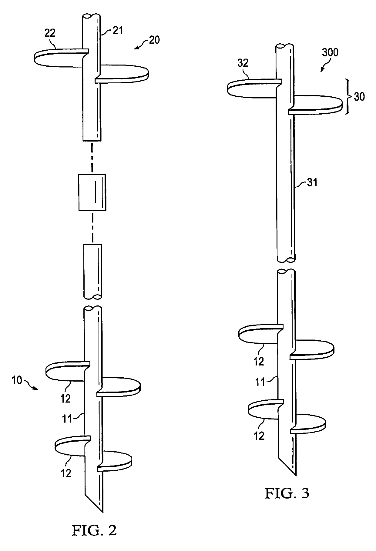
[0045]Embodiments of the present invention provide lateral stability for a load bearing pier disposed in the ground. The piers may support structures that are above, below, or partially above and partially below the ground. These structures may include residential and commercial buildings, light poles, telephone poles, roads, road signs etc. The piers are metallic and may be of various types such as driven piers, helical piers, etc. Further, these piers may be hollow piers, solid piers, round piers, rectangular piers, polygonal piers, the like, and combinations thereof.

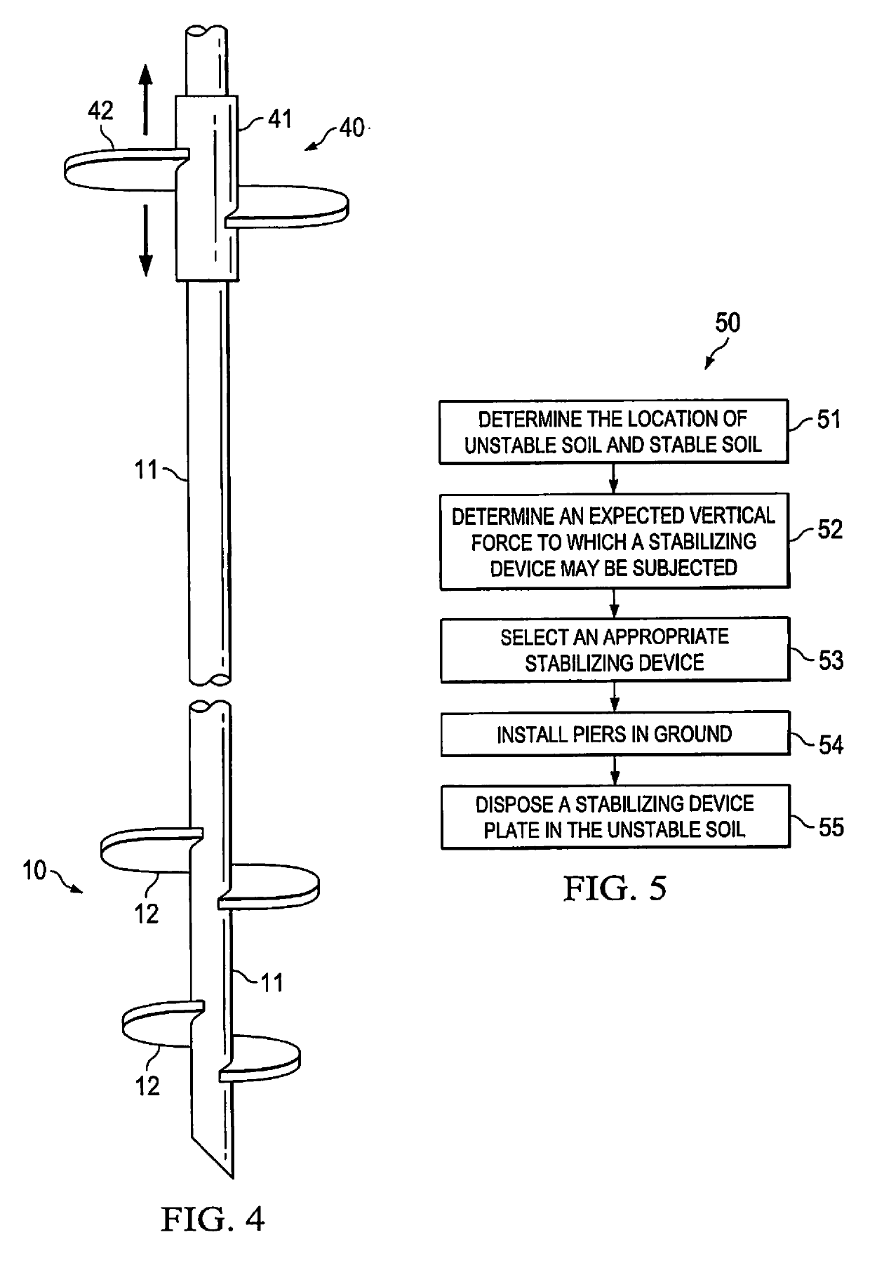
[0046]According to embodiments of the invention, a stabilizing device (that includes a stabilizing plate) is used to provide lateral support to a pier and to the structure the pier supports. In operation, when a lateral force is imposed on the pier, the pier, in turn, imposes that lateral force on the stabilizing device. Under this lateral force, the stabilizing device, in cooperation with soil surrounding the stabili...


PUM


Abstract

A device for stabilizing a metal pier installed in the ground. The device includes a device to provide lateral support to the pier and a shaft configured so that a force imposed, parallel to an axis of the pier, on the device is not imposed on the pier. A method of stabilizing a pier installed in ground to support a structure. The method includes determining the location of an unstable soil zone of the ground and a stable soil zone of the ground. The method also includes placing a stabilizing plate in the unstable soil zone to provide lateral support to the pier. A device configured to lift a foundation slab above the ground. The device includes a lifting bolt and apparatus that restricts lateral deflection of the pier when a torque is applied to the lifting bolt to raise the slab. A method of stabilizing soil around a pier.

Description

CROSS-REFERENCE TO RELATED APPLICATION[0001]The present application is a division of U.S. patent application Ser. No. 15 / 232,170, filed Aug. 9, 2016 and entitled, “SYSTEMS AND METHODS FOR INSTALLING AND STABILIZING A PIER,” the disclosure of which is incorporated by reference herein in its entirety.TECHNICAL FIELD[0002]The present application relates to narrow (outer dimension <6″) manufactured metal piers installed in the ground to support structures. More specifically, the application relates to systems and methods of installing and stabilizing metal piers.BACKGROUND OF THE INVENTION[0003]The quality of a structure, whether it is a house, apartment building or commercial office building, is inextricably tied to its foundation. If the structure is not built on a proper foundation, the rest of the structure, even if properly constructed, is likely to show defects over time. When foundations are constructed directly on soils or on the ground, it creates an unstable environment for...

Claims


Application Information

Patent Timeline
Patent Type & Authority Patents(United States)
IPC IPC(8): E02D27/34E02D27/32E02D31/10B66F3/08E02D5/56E02D3/12E02D5/22E02D7/00E02D35/00E02D7/22
CPCE02D5/223E02D27/34E02D35/005E02D5/56E02D3/12E02D31/10E02D7/00B66F3/08E02D27/32E02D7/22
Inventor CHILDRESS, TONY H.PINGREE, STEVENFONTAINE, JAMES
Owner TELLA FIRMA
Learn More