
Three parameter damper anisotropic vibration isolation mounting assembly

a technology of anisotropic vibration and mounting assembly, which is applied in the direction of machine/engine, machine supports, manufacturing tools, etc., can solve the problems of vibration of the overall system associated with the rotating machinery, vibrations that have a detrimental effect on both the performance of the rotating machinery and the comfort, and achieve the effect of reducing the transmission of vibrations

Active Publication Date: 2016-03-29
HONEYWELL INT INC
View PDF80 Cites 31 Cited by
  • Summary
  • Abstract
  • Description
  • Claims
  • Application Information

AI Technical Summary

Benefits of technology

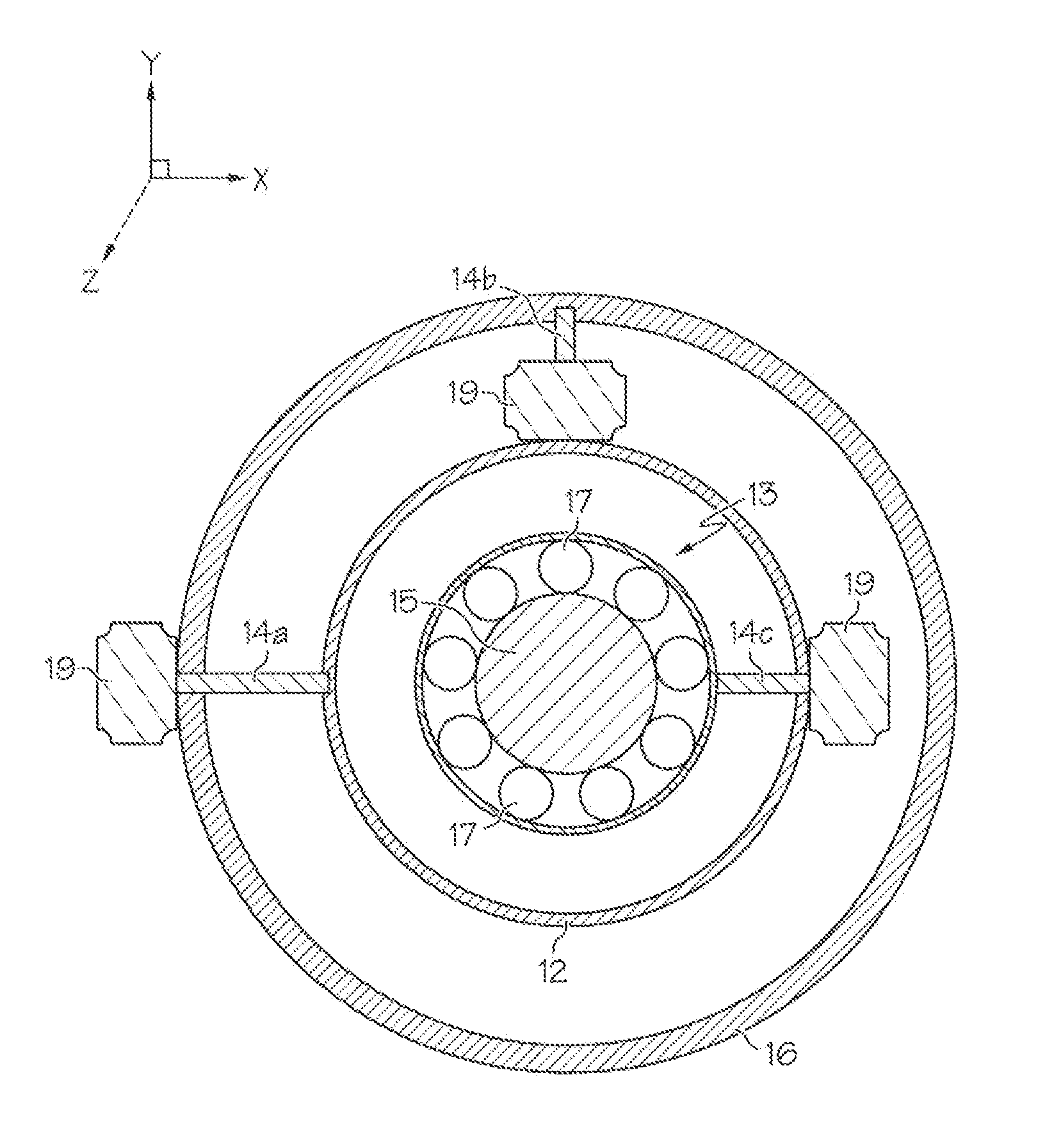
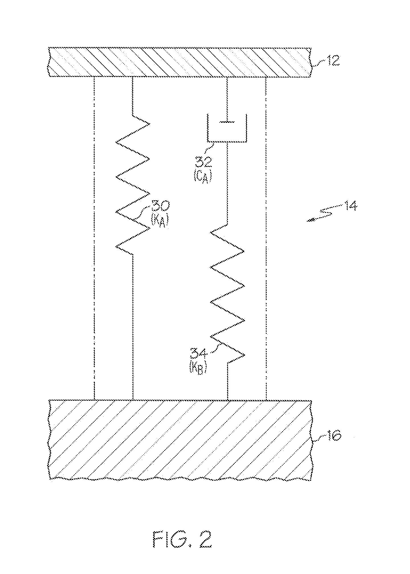
[0007]Anisotropic vibration isolation mounting assemblies for isolating vibrations in a rotating machine are provided. In one embodiment, the mounting assembly includes at least two three-parameter vibration isolators each having a first end and a second end, each first end configured for attachment to the rotating member assembly or the rotating member assembly housing, each second end configured for attachment to the rotating member assembly housing when the first end is configured for attachment to the rotating member assembly or to the system interface member when the first member is configured for attachment to the rotating member assembly housing. The at least two three-parameter vibration isolators are tuned anisotropically to minimize transmission of vibrations during operation of the rotating machine.
[0008]In another embodiment, disclosed is a gas turbine engine assembly configured to be mounted to an airframe. The gas turbine engine assembly includes a gas turbine engine, the gas turbine engine comprising a rotor bearing assembly, a rotor bearing housing, and an engine casing. The assembly further includes at least three three-parameter vibration isolators each having a first end and a second end, each first end configured for attachment to the rotor bearing assembly or the rotor bearing housing, each second end configured for attachment to the rotor bearing housing when the first end is configured for attachment to the rotor bearing assembly or to the engine casing when the first member is configured for attachment to the rotor bearing housing. The at least three three-parameter vibration isolators are tuned anisotropically to minimize transmission of vibrations from the gas turbine engine to the airframe during operation of the gas turbine engine.

Problems solved by technology

In addition, rotating machinery can experience non-synchronous responses due to de-stabilizing forces, such as a change in direction of travel (directional acceleration) or jarring forces such as air turbulence or uneven pavement, among others.
These forces (synchronous and non-synchronous) can result in vibration of the overall system associated with the rotating machinery.
Such vibrations have a detrimental effect on both the performance of the machinery and the comfort of persons who may be present on-board a vehicle associated with the rotating machinery (e.g., airplane, helicopter, automobile, etc.).
Because vibrations can introduce eccentricity in the rotation, vibrations can degrade the performance of the engine.
This degraded performance can be manifest as a decrease in thrust, which can, in turn, increase the length of a flight as well as the fuel required.
While not harmful, vibrations can be an unpleasant aspect of travel for the occupants.
SFDs are not ideal because they offer sub-optimal damping characteristics while still requiring oil and maintenance.
Additionally, the use of SFDs requires tolerancing for positioning of the rotor shaft and bearings that can introduce variations in the center of rotation of the shaft, further reducing performance.
Isotropic support systems, however, lack the ability to provide effective vibration isolation at the lowest frequencies that are typically associated with noise generation in the passenger cabin of an associated vehicle.
Furthermore, isotropic support systems lack the ability to tune support with regard to expected directional accelerations in the system.

Method used


Image

  • Three parameter damper anisotropic vibration isolation mounting assembly
  • Three parameter damper anisotropic vibration isolation mounting assembly
  • Three parameter damper anisotropic vibration isolation mounting assembly

Examples


example

[0042]An exemplary implementation of an anisotropic vibration isolation mounting assembly is depicted in FIG. 8 in a simplified cross-sectional view of a gas turbine engine (GTE) 818 including an anisotropic vibration isolation mounting assembly 820. By way of example, GTE 818 is illustrated in FIG. 8 as a two spool turbofan engine including an intake section 822, a compressor section 824, a combustion section 826, a turbine section 828, and an exhaust section 830. Intake section 822 includes an intake fan 832 mounted in a nacelle assembly 834. In the illustrated example, compressor section 824 includes a single compressor 836, which is rotatably disposed within an engine case 838 mounted within nacelle assembly 834. Turbine section 828 includes a high pressure (HP) turbine 840 and a low pressure (LP) turbine 842, which are rotatably disposed within engine case 38 in flow series. Compressor 836 and HP turbine 840 are mounted to opposing ends of an HP shaft or spool 844, and intake f...


PUM

PropertyMeasurementUnit
anisotropicaaaaaaaaaa
circumferential distancesaaaaaaaaaa
vibration damping parametersaaaaaaaaaa

Abstract

An anisotropic vibration isolation mounting assembly includes at least two three-parameter vibration isolators each having a first end configured for attachment to a rotating member assembly or a rotating member assembly housing and each having a second, opposing end configured for attachment to the rotating member assembly housing where the first end is configured for attachment to the rotating member assembly or to a system interface member where the first member is configured for attachment to the rotating member assembly housing. The at least two three-parameter vibration isolators are tuned anisotropically to minimize the transmission of vibrations during operation of the rotating machine.

Description

STATEMENT REGARDING FEDERALLY SPONSORED RESEARCH OR DEVELOPMENT[0001]This invention was made with Government support under W911W6-10-2-0008 awarded by the U.S. Army Aviation Applied Technology Directorate. The Government has certain rights in the invention.TECHNICAL FIELD[0002]Embodiments of the subject matter described herein relate generally to mounting assemblies. More particularly, embodiments of the subject matter relate to anisotropic vibration isolation assemblies and mounting assemblies for rotating machinery.BACKGROUND[0003]Vibrations are caused in the normal operation of various types of rotating machinery, for example aircraft turbine engines and other turbomachinery, rotating devices deployed on-board satellite and other spacecraft for attitude adjustment purposes, such as control moment gyroscopes and reaction wheels, automobile turbochargers, generators and pumps, and other rotating machinery. When machinery rotates, there can be loads or forces created due to imbalanc...

Claims


Application Information

Patent Timeline
Patent Type & Authority Patents(United States)
IPC IPC(8): F01D25/28F16F15/02F02C7/20F16F15/023
CPCF16F15/023F01D25/28F05D2260/96Y10T29/49826F16F15/131F16C2360/23F16C27/04
Inventor MEACHAM, WALTER, LEEBRIDGES, ERICMARGOLIS, ALAN
Owner HONEYWELL INT INC
Learn More