
Long range electromagnetic radiation sensor having a control system to heat and/or ionize the air within three-dimensional portions of an atmospheric volume

a control system and electromagnetic radiation technology, applied in the field of long-range sensor apparatus, can solve the problems of inability to achieve, inability to meet the requirements of the overall apparatus, and fixed optical properties and capabilities of conventional sensors, so as to facilitate fine tuning of atmospheric elements and reduce or eliminate deviations

Active Publication Date: 2019-11-26
BAE SYSTEMS PLC
View PDF27 Cites 0 Cited by
  • Summary
  • Abstract
  • Description
  • Claims
  • Application Information

AI Technical Summary

Benefits of technology

The present invention is a new technology for controlling the properties of an electromagnetic radiation beam in an atmospheric volume. By using a special lens design and heating or ionizing selected portions of the lens, the refractive index of the surrounding air is reduced, creating a converging effect that results in improved beam quality. The technology also includes an atmospheric monitoring module to compensate for atmospheric distortion and a quality monitoring module to dynamically adjust the beam steering / splitting and power of the electromagnetic radiation source to ensure consistent and high-quality performance. The technical effects of this technology include improved beam quality, reduced distortion, and improved performance of the atmospheric element.

Problems solved by technology

Thus, the optical properties and capabilities of conventional sensors are fixed and limited by physical constraints.
On the other hand, there is an ongoing desire to increase the range and angular resolution of telescopes and other long range sensors, which can currently only effectively be achieved by increasing the size of the overall apparatus, which can be undesirable in many applications and, in others, simply not practicable.
Such deviation may be caused by atmospheric distortion or otherwise.

Method used


Image

  • Long range electromagnetic radiation sensor having a control system to heat and/or ionize the air within three-dimensional portions of an atmospheric volume
  • Long range electromagnetic radiation sensor having a control system to heat and/or ionize the air within three-dimensional portions of an atmospheric volume
  • Long range electromagnetic radiation sensor having a control system to heat and/or ionize the air within three-dimensional portions of an atmospheric volume

Examples


Embodiment Construction

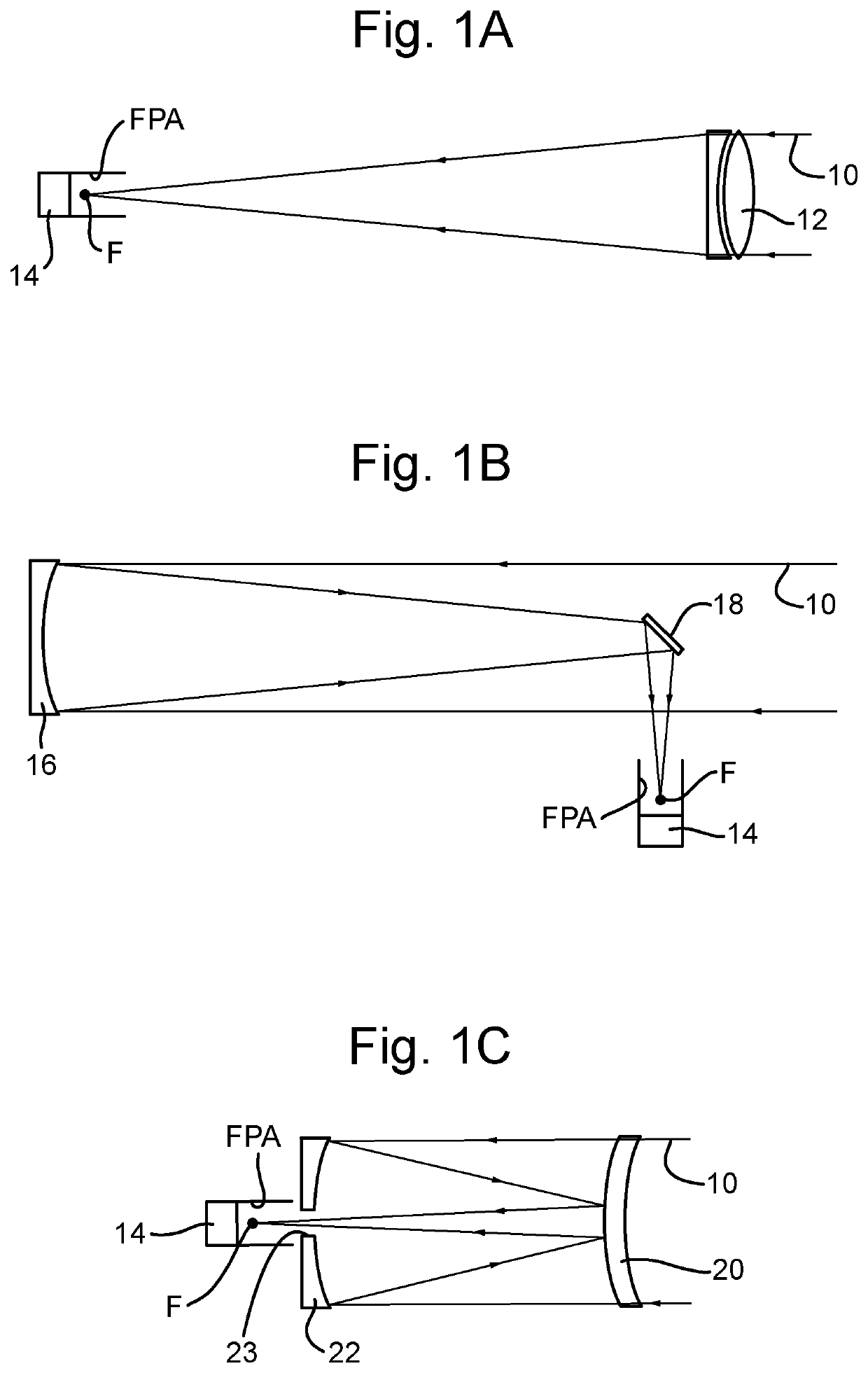
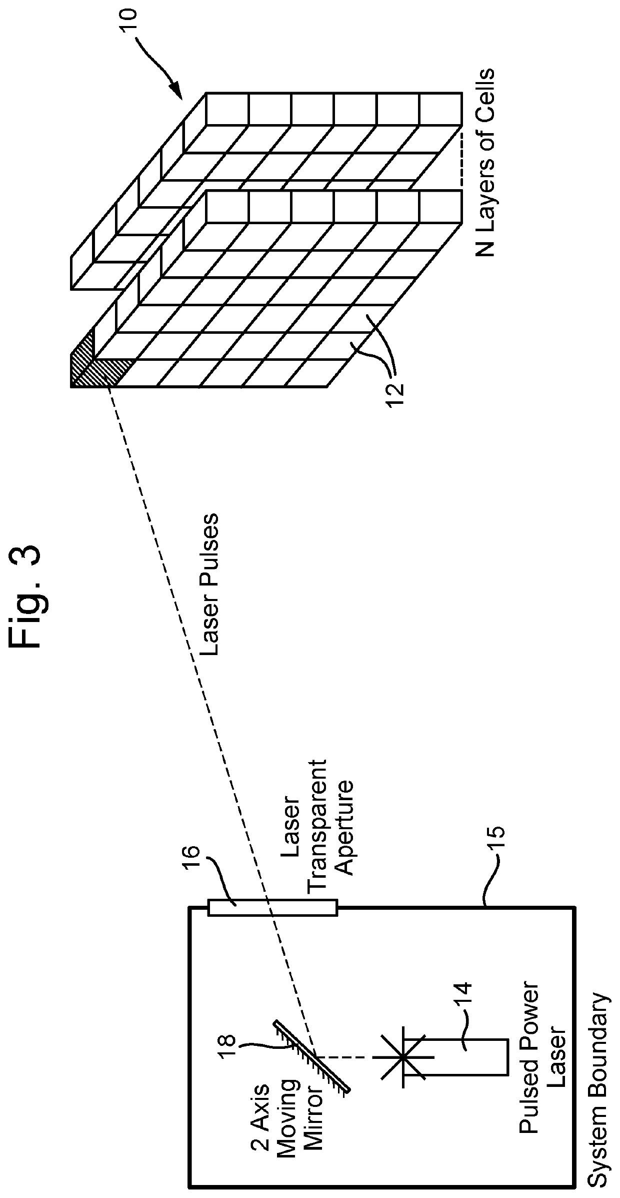
[0036]Thus, aspects of the present invention operate on the principle of using one or more laser devices to selectively alter the refractive index and / or cause ionisation of portions of a three-dimensional area of the atmosphere remote from the laser device(s) so as to create or simulate an optical component of a desired size and having selected optical properties for use as the primary objective optical element of a long range sensor apparatus.

[0037]In general, and referring to FIG. 2 of the drawings, the area of the atmosphere in which an optical component is required to be created can be considered as a cell matrix 10 comprised of M rows and N columns or layers of ‘cells’12, wherein a cell is simply a predefined three-dimensional portion of the matrix. In the example shown, each cell is identical in size and shape, but this is not essential, and the present invention is not necessarily intended to be limited in this regard. It will also be appreciated that the number of cells in ...


PUM

PropertyMeasurementUnit
shapeaaaaaaaaaa
refractive indexaaaaaaaaaa
volumeaaaaaaaaaa

Abstract

A long range electromagnetic radiation sensor apparatus comprising a sensing system for receiving electromagnetic radiation signals from an object or area of interest and at least one electromagnetic radiation sensor, the apparatus further comprising an electromagnetic radiation source and a control system configured to cause electromagnetic radiation from said source to be applied to a selected plurality of three-dimensional portions of an atmospheric volume between said optical system and said object or area of interest (204) so as to heat and / or ionise the air within said portions, wherein said selected portions are spatially located together in a three-dimensional configuration so as to simulate an electromagnetic radiation path modifying device (202) for capturing said electromagnetic signals from said object or area of interest and directing and / or converging said captured signals toward said electromagnetic radiation sensor of said sensing system.

Description

RELATED APPLICATIONS[0001]This application is a national phase application filed under 35 USC § 371 of PCT Application No. PCT / GB2016 / 050967 with an International filing date of Apr. 7, 2016 which claims priority of GB Patent Application 1506081.7 filed Apr. 10, 2015 and EP Patent Application 15275114.5 filed Apr. 10, 2015. Each of these applications is herein incorporated by reference in its entirety for all purposes.FIELD OF THE INVENTION[0002]This invention relates generally to a long range sensor apparatus and method of providing same for use in receiving electromagnetic signals, such as visible light from a scene as required in, for example, telescopes used in astronomy or image capture systems on airborne platforms.BACKGROUND OF THE INVENTION[0003]Telescopes and similar long range sensing devices are well known. Such devices typically comprise a primary objective lens, spaced apart from the main optical system and configured to collect photons and converge or otherwise guide a...

Claims


Application Information

Patent Timeline
Patent Type & Authority Patents(United States)
IPC IPC(8): G02F1/29G02B27/09G02B23/02
CPCG02F1/29G02B23/02G02B27/0944G02B27/0955G02B27/0977G02F1/293
Inventor COLOSIMO, NICHOLAS GIACOMO ROBERT
Owner BAE SYSTEMS PLC
Learn More