
Apparatus and method for generating 3-D data for an anatomical target using optical fiber shape sensing

a technology of optical fiber and shape sensing, applied in the field of optical fiber position sensing, can solve the problems precision, and achieve the effect of high degree of accuracy

Active Publication Date: 2019-11-19
INTUITIVE SURGICAL OPERATIONS INC
View PDF13 Cites 32 Cited by
  • Summary
  • Abstract
  • Description
  • Claims
  • Application Information

AI Technical Summary

Benefits of technology

The patent describes a technology that uses a fiber housing with multiple shape sensing cores and a single optical core to provide accurate measurements in a small and cost-effective device. The technology can be used to measure the distribution of tissue at a surgical site or identify sub-surface features. The fiber housing includes a collimator for collimating light and a tunable light source for projecting light over a range of frequencies. The reflected light is detected and processed to determine the position and pointing direction of the fiber housing, which is used to determine the position of the current point in three dimensions. The technology can be used to generate a three-dimensional data set of anatomical targets or navigate a cavity in the anatomical target. The patent also describes compensating the data set for motion of the anatomical target tissue and detecting the position of points on the outside of the anatomical target in three dimensions.

Problems solved by technology

Unfortunately, known tomography approaches require that each of the transmitter locations and detector locations is known with a high degree of accuracy and precision.

Method used


Image

  • Apparatus and method for generating 3-D data for an anatomical target using optical fiber shape sensing
  • Apparatus and method for generating 3-D data for an anatomical target using optical fiber shape sensing
  • Apparatus and method for generating 3-D data for an anatomical target using optical fiber shape sensing

Examples


Embodiment Construction

[0037]The technology described in this application provides three dimensional scanning inside and / or outside a human, animal, or other organic or inorganic anatomical target using a paired shape sensing fiber and single-core fiber. The shape sensing fiber provides position and orientation information, and the single-core fiber provides distance or range information to the point(s) on or in the anatomical target being scanned.

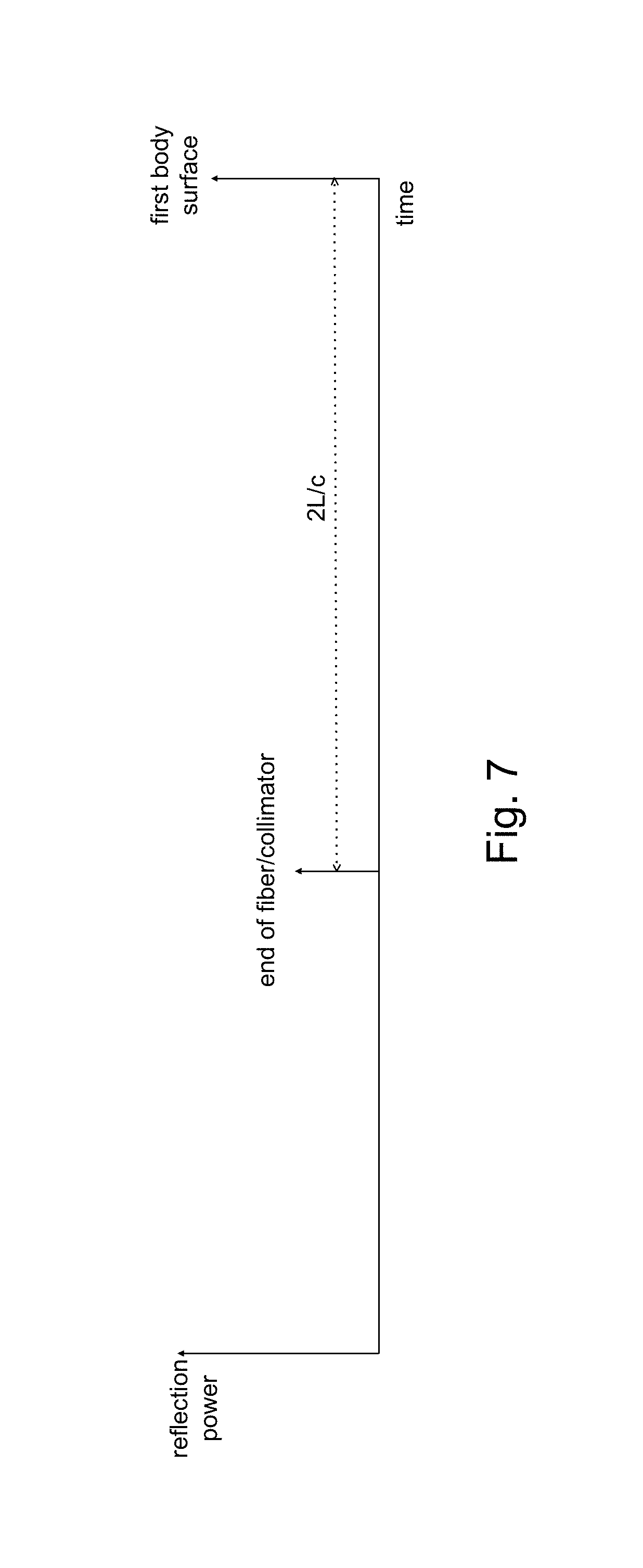
[0038]The shape sensing fiber allows for the precise determination of the location and pointing direction of the single-core fiber optical transmitter inside or outside an anatomical target using optical frequency domain reflectometry (OFDR) technology. The single-core fiber optical transmitter includes a collimator at its transmitting (distal) end and provides a distance to a current point in or on the anatomical target from light back-scattered into the collimator and processed using OFDR. The position of the current point in or on the anatomical target in thr...


PUM


Abstract

A fiber housing includes multiple shape sensing cores and a single optical core. A distal end of the fiber housing is positionable to direct the single optical core to a current point of an anatomical target. Collimated light over a first range of frequencies is projected from the single optical core to the current point. OFDR is used to detect reflected light scattered from the current point and to process the detected light to determine a distance to the current point. Light over a second range of frequencies is projected through the multiple shape sensing optical cores to the distal end of the fiber housing. OFDR is used to measure light reflected from the distal end of the fiber housing back through the multiple shape sensing optical cores and to process the measurement to determine a position in three dimensional space of the distal end of the fiber housing and a pointing direction of the distal end of the fiber housing. A position in three dimensional space of the current point is determined based on the determined position in three dimensional space of the distal end of the fiber housing, the pointing direction of the distal end of the fiber housing, and the determined distance.

Description

RELATED APPLICATIONS[0001]This application is the U.S. national phase of International Application No. PCT / US2016 / 065596 filed Dec. 8, 2016, which designated the U.S. and claims benefit to U.S. Provisional Patent Application 62 / 266,879, entitled “APPARATUS AND METHOD FOR GENERATING 3-D DATA FOR AN ANATOMICAL TARGET USING OPTICAL FIBER SHAPE SENSING,” filed Dec. 14, 2015, the entire contents of each of which are hereby incorporated by reference.TECHNICAL FIELD[0002]The technology relates to optical fiber position sensing based on interferometric measurements to provide position and orientation information.INTRODUCTION[0003]Optical strain sensing is useful for measuring physical deformation of an optical fiber caused by, for example, the change in tension, compression, or temperature of the optical fiber. A multi-core optical fiber is composed of several independent waveguides or cores embedded within a single fiber. A continuous measure of strain along the length of a core can be der...

Claims


Application Information

Patent Timeline
Patent Type & Authority Patents(United States)
IPC IPC(8): G01B9/02A61B5/1459A61B5/06A61B5/107A61B3/107A61B5/00A61B3/10G01M11/00A61B5/026
CPCG01M11/3172A61B5/0261A61B5/1076A61B3/102A61B5/0066A61B5/1459G01B9/0209A61B5/1072A61B3/107A61B5/061
Inventor FROGGATT, MARK E.SANBORN, ERIC E.BARBAGLI, FEDERICO
Owner INTUITIVE SURGICAL OPERATIONS INC
Learn More