
Self-calibrating projection geometry for volumetric image reconstruction

a volumetric image and projection geometry technology, applied in the field of medical imaging, can solve the problems of geometric calibration errors, geometric distortion, other artifacts, and other artifacts, and achieve the effects of improving the accuracy of geometric calibration

Active Publication Date: 2019-11-19
THE JOHN HOPKINS UNIV SCHOOL OF MEDICINE
View PDF0 Cites 3 Cited by
  • Summary
  • Abstract
  • Description
  • Claims
  • Application Information

AI Technical Summary

Benefits of technology

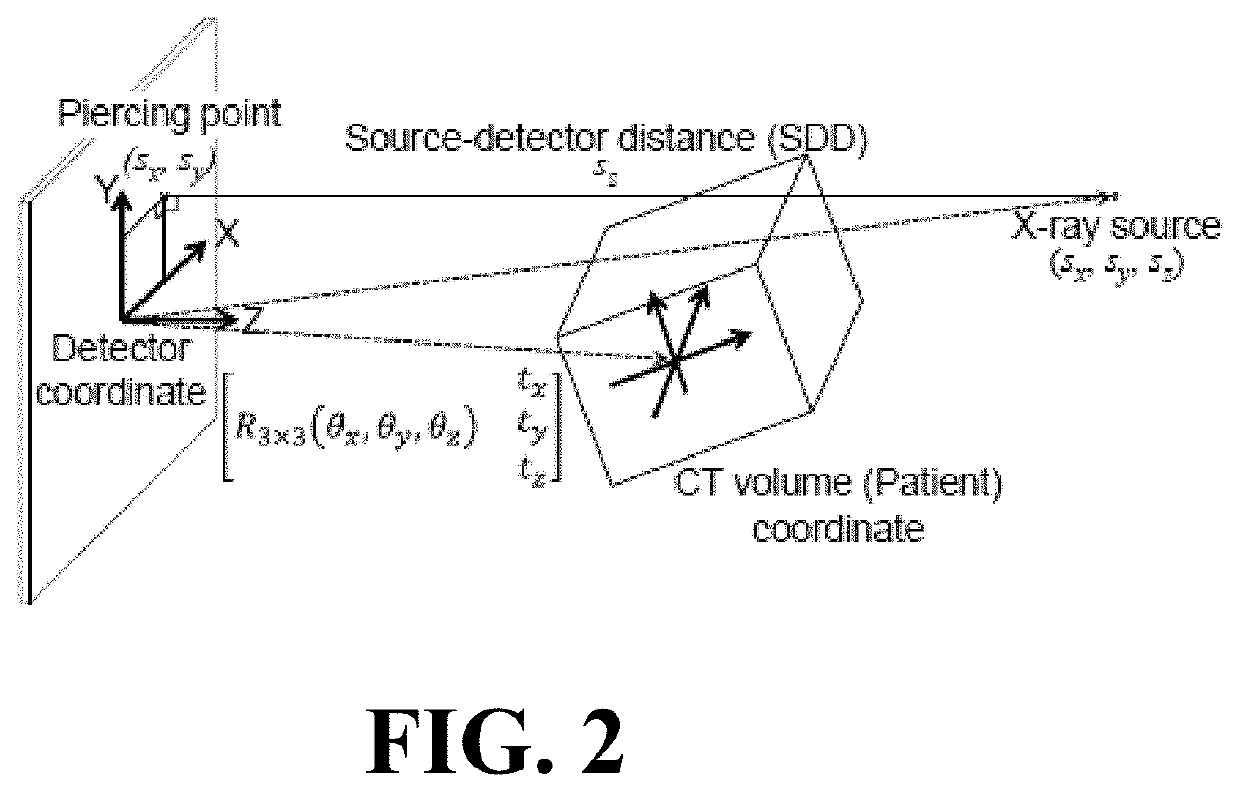
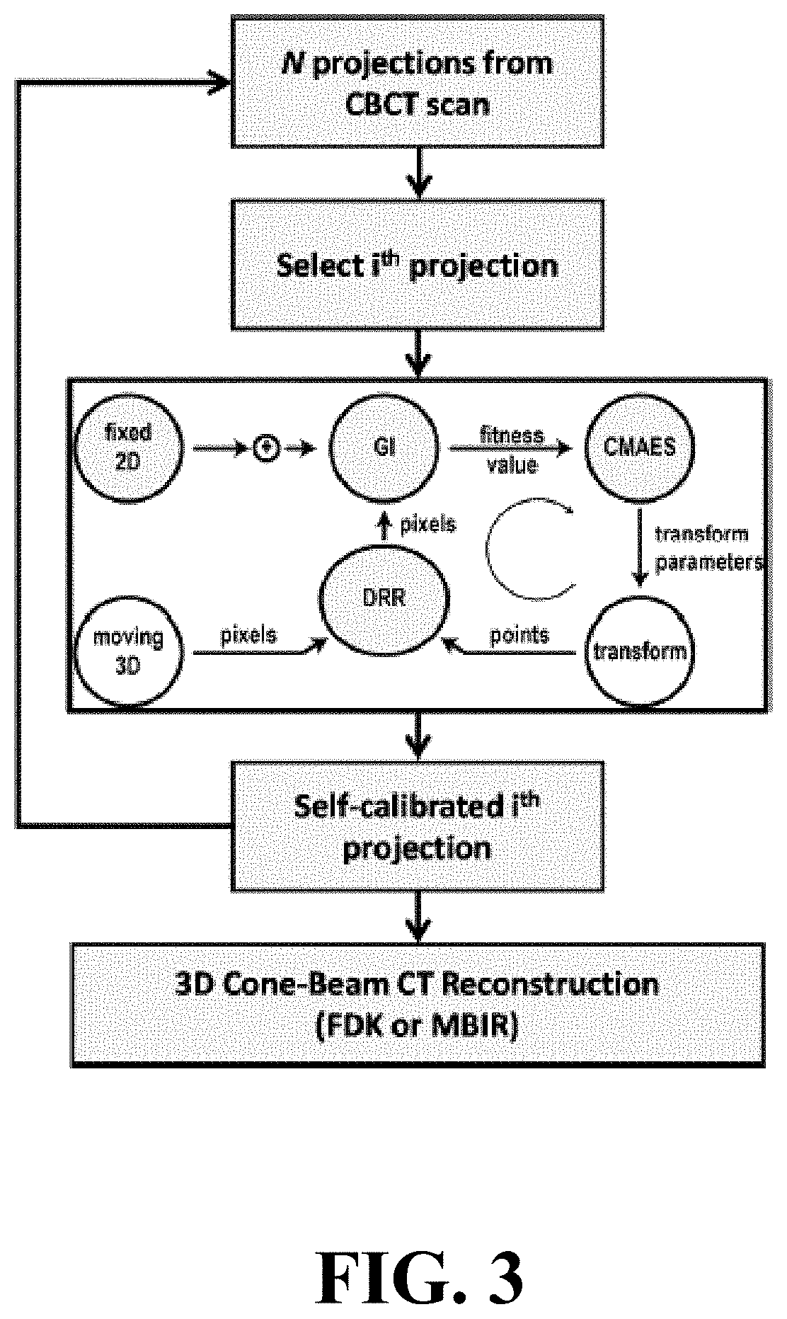
The present invention provides a method for self-calibrating the projection geometry for a volumetric image reconstruction of a patient using a cone-beam computed tomography (CBCT) scanner. This is achieved by selecting a prior volumetric representation of the patient, dividing the CBCT scan into projections, and applying a 9-degree-of-freedom geometric calibration of the selected projection. The method also includes generating a projection matrix from the geometric calibration and using it for generating a three-dimensional, volumetric reconstruction of the CBCT scan. The invention provides a system for self-calibrating the projection geometry of a patient using a CBCT scanner, which can improve the accuracy and reliability of the volumetric image reconstruction.

Problems solved by technology

However, errors in geometric calibration persist, resulting in blurry images, ring artifacts, geometric distortion, and other artifacts.
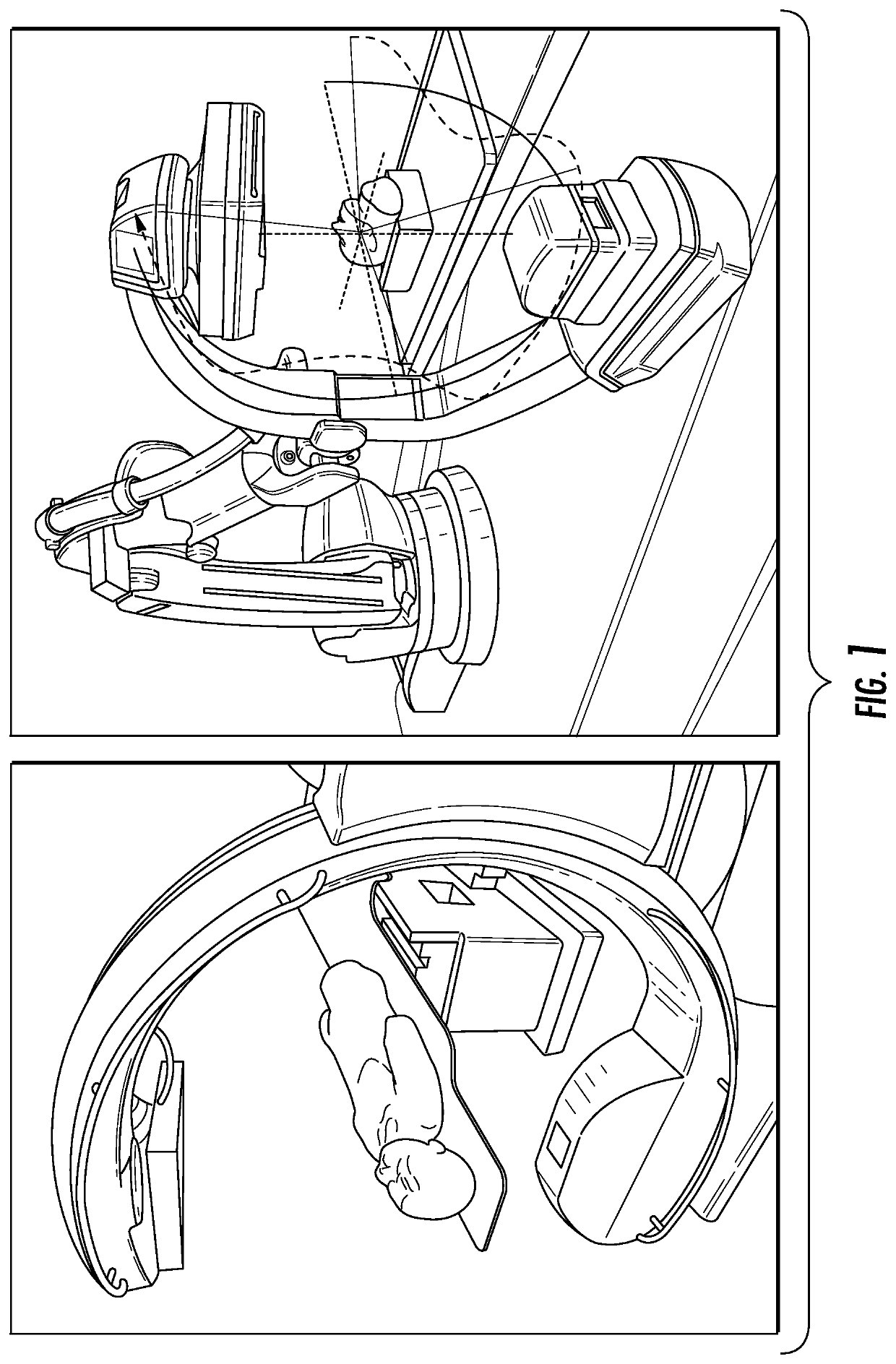
Reasons for such errors include overly simplistic models of system geometry, change introduced to the system (whether intentional or unintentional), scan-to-scan variability such as system jitter, and non-reproducible orbits such as custom-designed trajectories.
Calibrating the projection geometry for fixed-geometry systems is inherently a 6-DOF problem (per projection) given that the intrinsic parameters are constrained and can be well-calibrated; however, the intrinsics are known to vary from scan to scan for reasons including gravity-induced flex and system jitter.
However, there may be a change in geometry or other inconsistencies between the previously acquired geometric calibration scan and the current patient scan, or the geometry / trajectory may be irreproducible altogether (e.g., custom-designed trajectories on the Zeego).
Scan-specific (“on-line”) geometric calibration methods have been proposed that simultaneously acquire fiducial markers with the patient scan; however, this requires placing markers on or next to the patient and within the imaging field of view, which is a cumbersome (and sometimes impossible) process that superimposes markers onto the projections and is detrimental to image reconstruction, or are limited to niche applications where small high-contrast objects are already within the patient (e.g., brachytherapy).
Other scan-specific methods propose the use of additional sensors to capture the source and detector positions, but introduce additional hardware and workflow complexity.
Image-based “auto-focus” methods require time-consuming reconstructions in each function evaluation and / or optimize image quality metrics over a set of few simple parameters that describe the overall geometry of the system (e.g., assuming a circular orbit), rather than the full geometry of each projection.
In this case, the patient himself can be used as a fiducial, which obviates the need for external fiducials or trackers that are often inaccurate and a burden to workflow.
However, none can provide a complete, scan-specific description of the system geometry without introducing additional workflow complexities that can be cumbersome (and sometimes impossible) to use.
For example, the “off-line” calibration methods cannot be used for non-reproducible trajectories, nor can they account for scan-to-scan variability such as system jitter.
The “on-line” calibration methods require use of additional markers or hardware that interferes with workflow and often with image reconstruction.
Lastly, the “auto-focus” methods do not provide a complete geometric description and instead usually only tune a few parameters due to the computational challenges associated with tuning all available parameters.

Method used


Image

  • Self-calibrating projection geometry for volumetric image reconstruction
  • Self-calibrating projection geometry for volumetric image reconstruction
  • Self-calibrating projection geometry for volumetric image reconstruction

Examples


experiment 1

[0093]

[0094]Cylinder phantom on imaging bench. Experiment 1 involved the cylinder phantom imaged on the CBCT bench to test the feasibility of the self-calibration method and obtain quantitative analysis of basic performance. A circular orbit was used, with the nominal scan technique described above. A previous CBCT scan of the phantom formed the 3D image input to the self-calibration method, with the previous scan acquired with an angular offset in projection views so that the projections used in 3D reconstruction were not identical to those in 3D-2D registration.

experiment 2

[0095]

[0096]Anthropomorphic head phantom on imaging bench. Experiment 2 involved the anthropomorphic head phantom imaged on the CBCT bench to test the robustness of 3D-2D registration under more clinically / anatomically realistic conditions of x-ray scatter, image noise, and complexity of the subject. A previous scan of the head phantom on a diagnostic CT scanner (Siemens Somatom Definition, 120 kVp, 227 mAs, (0.46×0.46×0.40 mm3) voxels) formed the 3D image input to the self-calibration method.

experiment 3

[0097]

[0098]Anthropomorphic head phantom on robotic C-arm. Experiment 3 involved the anthropomorphic head phantom imaged on the Artis Zeego to test the method in a clinically realistic system geometry and orbit. A previous CBCT scan of the head phantom acquired using the Zeego formed the 3D image input to the self-calibration method. To challenge the method further, a realistic, pronounced change in image content was produced between the previous 3D image and the projection images acquired in the current CBCT scan—viz., a 2 mm diameter steel biopsy needle placed in the nasal sinuses and positioning the head with a strong) (˜30° canthomeatal tilt to mimic a typical clinical setup. The reference calibration (using the spiral BB phantom mentioned above) was performed by the system service engineer as part of regular preventative maintenance within 6 months of the current scan in accordance with standard clinical practice.


PUM


Abstract

The present invention is directed to a method for enabling volumetric image reconstruction from unknown projection geometry of tomographic imaging systems, including CT, cone-beam CT (CBCT), and tomosynthesis systems. The invention enables image reconstruction in cases where it was not previously possible (e.g., custom-designed trajectories on robotic C-arms, or systems using uncalibrated geometries), and more broadly offers improved image quality (e.g., improved spatial resolution and reduced streak artifact) and robustness to patient motion (e.g., inherent compensation for rigid motion) in a manner that does not alter the patient setup or imaging workflow. The method provides a means for accurately estimating the complete geometric description of each projection acquired during a scan by simulating various poses of the x-ray source and detector to determine their unique, scan-specific positions relative to the patient, which is often unknown or inexactly known (e.g., a custom-designed trajectory, or scan-to-scan variability in source and detector position).

Description

CROSS REFERENCE TO RELATED APPLICATIONS[0001]This application claims the benefit of U.S. Provisional Patent Application No. 62 / 297,255 filed Feb. 19, 2016, which is incorporated by reference herein, in its entirety.FIELD OF THE INVENTION[0002]The present invention relates generally to medical imaging. More particularly, the present invention relates to a method for self-calibrating projection geometry for volumetric image reconstruction.BACKGROUND OF THE INVENTION[0003]Tomographic imaging systems such as diagnostic CT scanners, tomosynthesis systems, and cone-beam CT (CBCT) systems require a known system geometry in order to perform accurate image reconstruction. Because image quality can be sensitive to sub-mm errors in geometry and system geometry can change over time, most CT / CBCT systems employ some form of routine (e.g., daily) geometric calibration to provide up-to-date system geometry for each patient acquisition. However, errors in geometric calibration persist, resulting in...

Claims


Application Information

Patent Timeline
Patent Type & Authority Patents(United States)
IPC IPC(8): G06K9/00A61B6/03A61B6/00A61B6/02
CPCA61B6/025A61B6/032A61B6/466A61B6/5205A61B6/4085A61B6/4441A61B6/584A61B6/501
Inventor SIEWERDSEN, JEFFREY H.OTAKE, YOSHITOSTAYMAN, JOSEPH WEBSTERUNERI, ALIWANG, ADAM S.OUADAH, SARAH
Owner THE JOHN HOPKINS UNIV SCHOOL OF MEDICINE
Learn More