Cutting assembly for a boring device

a cutting assembly and boring device technology, applied in the direction of directional drilling, drilling with mechanical conveying, borehole/well accessories, etc., can solve the problems of affecting drilling efficiency, affecting drilling, and affecting drilling, so as to reduce the size of cuttings being moved and prevent frac-out

Active Publication Date: 2019-11-05
BARBCO
View PDF38 Cites 4 Cited by
  • Summary
  • Abstract
  • Description
  • Claims
  • Application Information

AI Technical Summary

Benefits of technology

[0008]In the presently disclosed apparatus and method pressurized air may be used to discharge cuttings produced by the disclosed cutting assembly. The cutting assembly may include a front cutting head and a larger diameter rear cutting head mounted on a shaft. An air passage defined through the cutting assembly may be placed in fluid communication with a pressurized remote air source and with a bore of a casing extending rearwardly from the cutting assembly. Pressurized air flows through the air passage and entrains cuttings produced by the front and rear cutting heads. A housing extends rearwardly from the larger diameter rear cutting head and an auger provided within the housing aids in directing cuttings into the casing. The auger rotates independently of the rest of the cutting assembly and may be configured to further reduce the size of the cuttings being moved thereby. A collar on the housing seals the borehole cut by the rear cutting assembly and aids in preventing frac-out.
[0013]The method may further comprise contacting the entrained cuttings with teeth provided on the auger; and reducing a size of the entrained cuttings with the teeth. The method may further comprise a step of adjusting back pressure in the first air passage and the second air passage by changing a pattern of holes in an end plate provided on the auger.

Problems solved by technology

The use of certain types of drilling fluids may present environmental hazards and may be prohibited by environmental laws or regulations in certain circumstances.
Although bentonite is non-toxic, the use of a bentonite slurry may be harmful to aquatic plants and fish and their eggs, as these may be smothered by the fine bentonite particles if discharged into waterways.
Other issues faced in drilling applications include that the terrain itself may cause disruptions to drilling.

Method used


Image

  • Cutting assembly for a boring device
  • Cutting assembly for a boring device
  • Cutting assembly for a boring device

Examples


Embodiment Construction

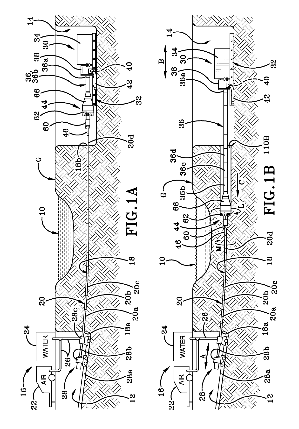
[0038]FIG. 1 shows an area of terrain or ground “G” that includes an environmental obstacle 10 under which it is necessary to drill a borehole in order to lay a length of pipe. The obstacle 10 in this particular instance is illustrated as a body of water such as a stream, a river, a pond or a lake. It will be understood, however, that obstacle 10 may represent any other type of obstacle such as roads, buildings, walls, and trees and so forth such that trenchless or horizontal directional drilling (HDD drilling) is desirable or required.

[0039]In order to conduct a drilling operation in ground “G”, a first pit 12 is dug in the ground “G” on one side of obstacle 10 and a second pit 14 is dug in ground “G” on the opposite side of obstacle 10. First pit 12 may be used to set up a control assembly 16 that may include a variety of different pieces of equipment at various times. Some of the equipment may be utilized to drill a pilot hole 18 from first pit 12 to second pit 14 and for inserti...


PUM


Abstract

A cutting assembly and method for drilling an underground borehole. The cutting assembly includes front and rear cutting heads of different diameters mounted on a shaft. An air passage defined through the cutting assembly may be placed in fluid communication with a pressurized remote air source and with a bore of a casing extending rearwardly from the cutting assembly. Pressurized air flows through the air passage and entrains cuttings produced by the front and rear cutting heads. A housing extends rearwardly from the larger diameter rear cutting head and an auger provided within the housing aids in directing cuttings into the casing. The auger rotates independently of the rest of the cutting assembly and may be configured to further reduce the size of the cuttings. A collar on the housing seals the borehole cut by the rear cutting assembly and aids in preventing frac-out.

Description

BACKGROUND OF THE INVENTIONTechnical Field[0001]The invention relates generally to an apparatus and method for drilling generally horizontal boreholes. More particularly, the invention is directed to a cutting assembly in which pressurized air is used to facilitate removal of the spoil or cuttings from the borehole. Specifically, the invention relates to a cutting assembly having a front cutting head and a larger diameter rear cutting head. A housing extends rearwardly from the rear cutting head and connects to a casing. An annular collar on the cutting assembly seals the borehole cut by the rear cutting head. Cuttings are moved through an air passage in the cutting assembly and into the casing using pressurized air and an independently rotating auger located in the housing.Background Information[0002]Underground boring machines have been used for many years in the drilling of generally horizontal boreholes. The machines may be used to drill boreholes that are substantially straight...

Claims


Application Information

Patent Timeline
Patent Type & Authority Patents(United States)
IPC IPC(8): E21B21/16E21B7/20E21B10/60E21B10/28E21B7/00E21B7/28E21B10/44E21B21/00E21B10/18E21B7/04
CPCE21B7/201E21B7/20E21B21/16E21B10/28E21B7/28E21B10/18E21B7/046E21B7/005E21B10/60E21B10/44E21B2021/005
Inventor BARBERA, ANTHONY R.
Owner BARBCO
Why Eureka
Try Eureka