
Panel

Active Publication Date: 2019-10-29
AKZENTA PANEELE PROFILE GMBH
View PDF26 Cites 2 Cited by
  • Summary
  • Abstract
  • Description
  • Claims
  • Application Information

AI Technical Summary

Benefits of technology

The patent text describes a panel with complementary edges that have butting surfaces that prevent unwanted displacement of the edges. The panel can also contain hollow microspheres to reduce density and weight, and a fiber material can be added for increased load-carrying capacity or stability. The carrier material can also be cut to size and can include a plurality of threads or webs for flexibility in adjustment and variation. The technical effects include improved stability, reduced weight, and increased load-carrying capacity.

Problems solved by technology

The butting join of panels which are fitted together can in practice turn out to be irregular.
Although panel edges are pressed together when they are adhesively bonded on a substrate inclined positions and gaps can occur, which disrupt a desired uniform appearance for a coating surface.

Method used


Image

  • Panel
  • Panel
  • Panel

Examples


Embodiment Construction

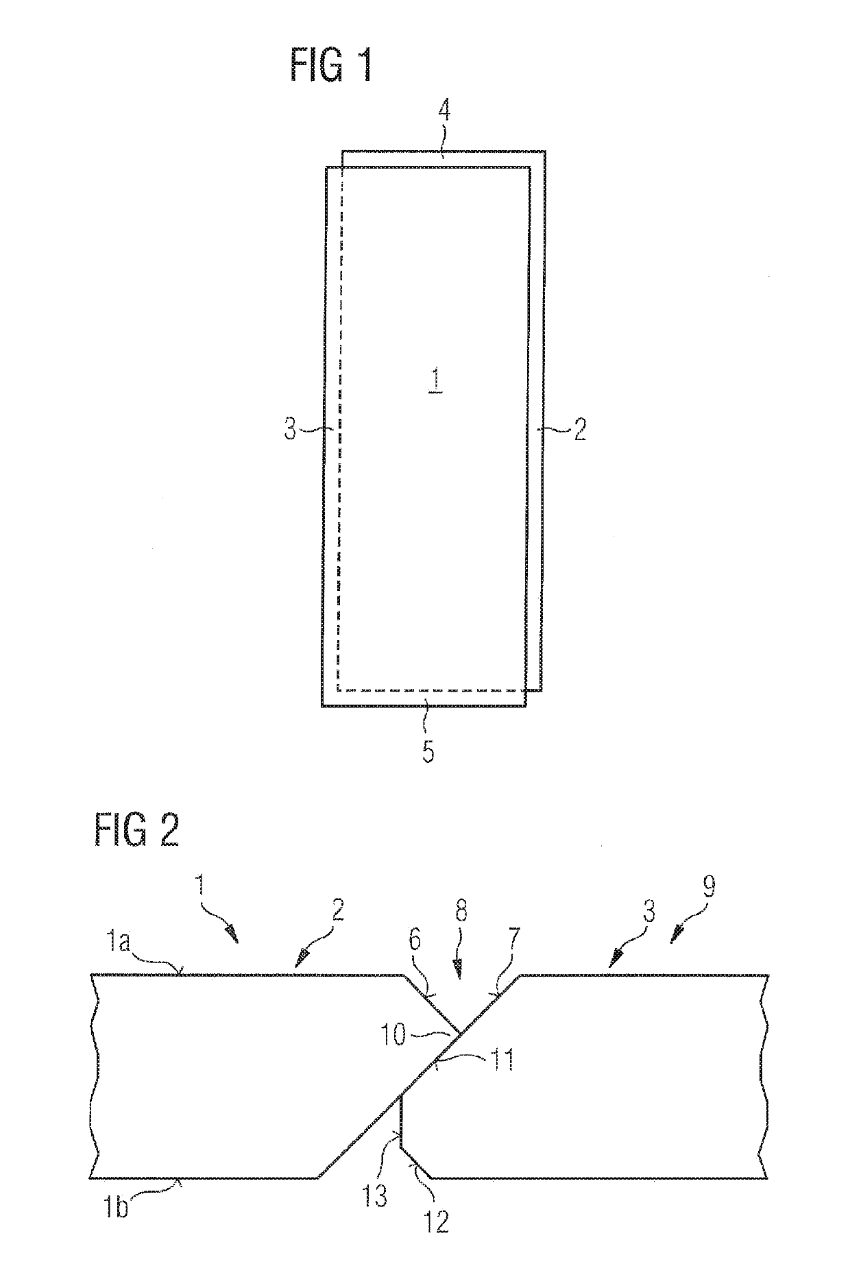
[0070]The example shown in FIG. 1 involves a panel 1 of a rectangular base surface. The panel has two pairs of edges, whose panel edges 2, 3 and 4, 5 respectively are respectively disposed in paired opposite relationship. The panel edges are provided with panel edges according to the invention.

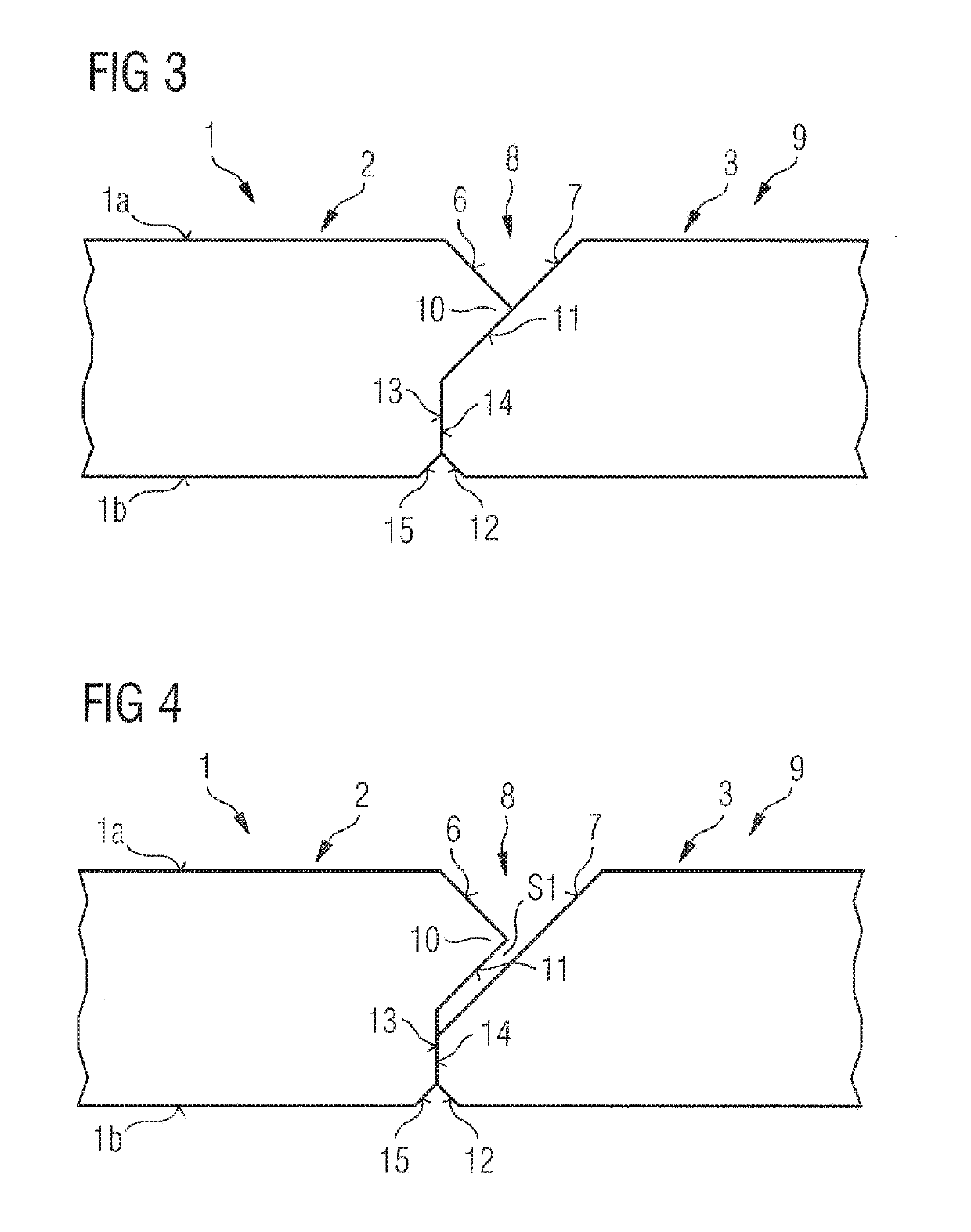
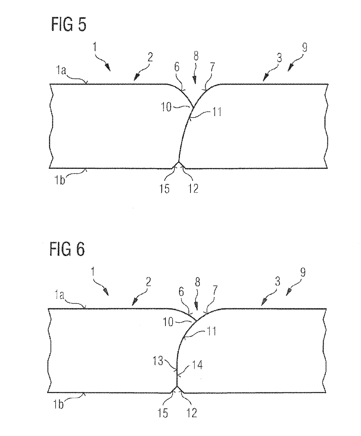
[0071]FIG. 2 shows oppositely disposed panel edges 2 and 3 of a panel 1. The panel has a panel top side 1a and a panel underside 1b. At the panel top side 1a the panel edge 2 is respectively provided with an edge break and the panel edge 3 is respectively provided with an edge break which is larger than the edge break of the panel edge 2. Both edge breaks are in the form of a 45° bevel. In the illustrated connected condition the small edge break 6 and a part of the large edge break 7 together form a V-shaped join 8 in a covering surface 9. In the connected condition a lower part of the large edge break 7 of the panel edge 3 is overlapped by the small edge break 6 of the oppositely disposed pan...


PUM


Abstract

A panel having a panel upper side and a panel lower side and at least two opposing panel edges, which have each an edge break on the panel upper side, the edge breaks forming in the connected state a joint in a covering surface. The edge break of one of the panel edges is formed larger than the edge break of the opposing panel edge, and a lower part of the large edge break of the one panel edge is overlapped in the connected state by the small edge break of the opposing panel edge.

Description

[0001]The present application is a 371 of International application PCT / EP2016 / 067445, filed Jul. 21, 2016, which claims priority of DE 10 2015 111 930.7, filed Jul. 22, 2015, the priority of these applications is hereby claimed and these applications are incorporated herein by reference.BACKGROUND OF THE INVENTION[0002]The invention concerns a panel having a panel top side and a panel underside and at least two mutually opposite panel edges, which respectively have an edge break at the panel top side, wherein the edge breaks in turn in the connected condition together form a join in a covering surface.[0003]The panels usually have decorative surfaces. In particular the invention relates to a panel of the above-indicated general kind which is intended for adhesive bonding to a supporting substrate. Such panels are used for example as floor panels and are glued on a floor screed and so forth. The mutually opposite panel edges of the proposed panel have contoured panel edges which are...

Claims


Application Information

Patent Timeline
IPC IPC(8): E04B2/00E04F15/02E04F13/08E04F15/04E04F15/18
CPCE04F15/02038E04F15/181E04F15/02155E04F13/0894E04F15/02033E04F15/042E04F2201/0107E04F2201/0115E04F2201/026E04F15/02E04F15/0215
Inventor LOEBEL, ARNESCHÄFERS, ERICH
Owner AKZENTA PANEELE PROFILE GMBH
Learn More