
Elevator device for intravenous solution

a technology of elevator device and intravenous solution, which is applied in the direction of intravenous device, infusion device, apparel, etc., can solve the problems of unsatisfactory traditional devices for supporting bags or bottles containing intravenous solution at the desired height, fixed configuration which is rather cumbersome, and no device is known which can be used in emergency rooms

Active Publication Date: 2019-10-22
A L M S MEDICAL SRL
View PDF19 Cites 1 Cited by
  • Summary
  • Abstract
  • Description
  • Claims
  • Application Information

AI Technical Summary

Benefits of technology

The technical effects of this patent text are as follows: 1. The invention provides a device that is easy to carry. 2. The invention provides a device that is highly versatile and effective. 3. The invention provides a device that is simple, quick, and cost-effective to obtain.

Problems solved by technology

However, these devices have a fixed configuration which is rather cumbersome, especially when their use is not required.
In particular, to date, no devices are known which can be used in emergency rooms, where instead an operator generally manually supports the fluid bag in a raised position.
In essence, traditional devices for supporting bags or bottles containing intravenous solutions at the desired height are not completely satisfactory in that they do not adequately combine technological aspects and functional requirements.

Method used


Image

  • Elevator device for intravenous solution
  • Elevator device for intravenous solution
  • Elevator device for intravenous solution

Examples


first embodiment

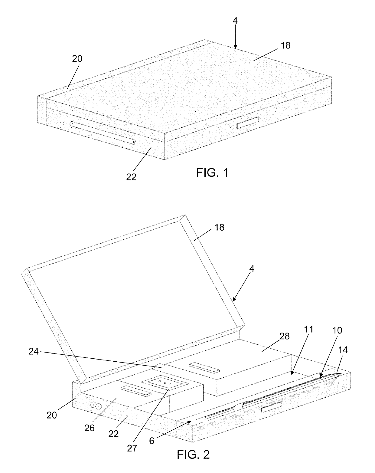
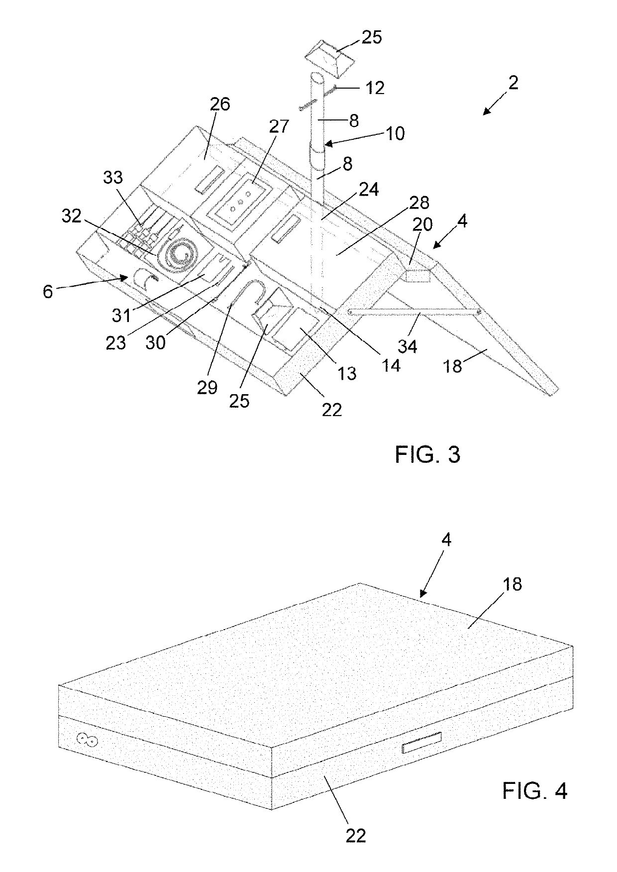
[0043]In particular, in the first embodiment shown in FIGS. 1 to 3, container 4 rests on a support surface with a longitudinal edge of base 22 and with the corresponding longitudinal edge of lid 18, as shown in FIG. 3.

[0044]Conveniently, the base 22 of container 4 and the lid 18 are maintained in the spread apart position by a pair of mutual connection and stabilization tie rods 34.

[0045]Then, once the stable supporting base has been created, the lower segment 8 of the assembled pole 10 is passed through hole 24 until the tip 14 of such a segment rests on or penetrates into the resting surface of the device.

[0046]Conveniently, the supporting base for the assembled pole 10 is thus stable while allowing free and easy access to the lower section of the pole itself.

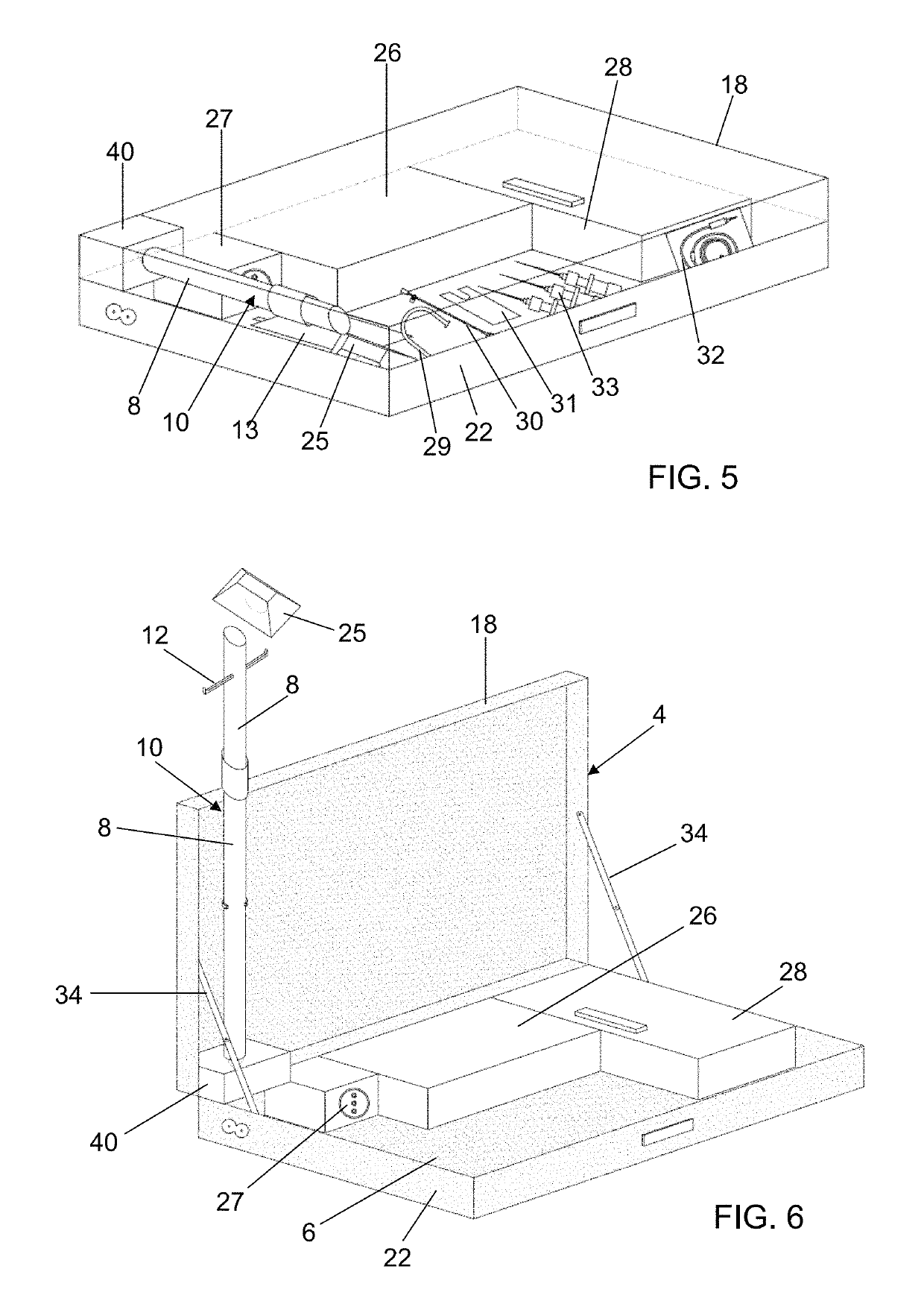
[0047]In a second embodiment shown in FIGS. 4 to 6, the device has all the features described above with reference to the first embodiment, and has the same operating mode, except for the lower end of pole 10 always remaining...

second embodiment

[0050]Also in this second embodiment, device 2 can take a first non-operating disassembled configuration, particularly suitable for transport. In this configuration, the folding lid 18 closes and superiorly covers base 22, and pole 10 is in the less extended / disassembled condition and is constrained, by means of the connecting block 40 thereof, to the lid 18 so as to be accommodated into the corresponding seat 6 provided into the base 22 of container 4.

[0051]When there is an operating need, the user switches device 2 from the disassembled, non-operating configuration to the assembled operating configuration. In particular, to this end, he / she lifts the lid 18 of container 4, preferably by tilting it by 90° with respect to base 22, so as to also cause the rotation of the corresponding block 40, associated with lid 18, and thus arrange the lower segment 8 of pole 10 in a substantially vertical position. Once this position has been reached, the remaining segments 8 are assembled togeth...


PUM


Abstract

An elevator device for intravenous solution includes an openable container with a base and a lid, a pole having at least two segments and adapted to define a more extended condition and a less extended condition, and a member supporting a bag or a bottle containing the intravenous solution. The elevator device is adapted to assume a first non-operating configuration, in which the pole in the less extended condition and the member are accommodated into a seat provided in the container, and a second operating configuration, in which the pole is in the more extended condition and the member is associated to the pole at an upper portion thereof, and in which the container defines a supporting base that inferiorly supports the pole and that is adapted to be stably positioned on a resting surface.

Description

FIELD OF THE INVENTION[0001]The present invention relates to an improved elevator device for intravenous solutions.BACKGROUND OF THE INVENTION[0002]Elevator devices for intravenous solution are known, better known as “i.v. stands”, which consist of a pole inferiorly associated with a base, generally provided with rollers, and also provided with one or more support arms for bags or bottles of fluid intended to be infused into the patient. In particular, the support arm with the corresponding fluid bag is positioned, even in an adjustable manner, at a suitable height along the pole in order to generate the prevalence needed for the fluid in the bag to be infused into the patient.[0003]However, these devices have a fixed configuration which is rather cumbersome, especially when their use is not required.[0004]Moreover, they are substantially adapted to be used only in hospitals or health resorts or anyway in places characterized by regular resting surfaces for the base of the pole. In ...

Claims


Application Information

Patent Timeline
IPC IPC(8): A61M5/14A45C11/00A45C9/00A45C13/02
CPCA45C9/00A45C13/02A45C11/00A61M5/1415A45C2200/15A61M5/14
Inventor CECCATO, SERENAZUCCOLIN, GIORGIA
Owner A L M S MEDICAL SRL
Learn More