
X-ray techniques using structured illumination

a structured illumination and x-ray technology, applied in the field of x-ray techniques using structured illumination, can solve the problems of reducing throughput, reducing throughput, and reducing throughput, so as to reduce unwanted signals, enhance signals, and increase x-ray flux

Active Publication Date: 2019-09-03
SIGRAY INC
View PDF477 Cites 20 Cited by
  • Summary
  • Abstract
  • Description
  • Claims
  • Application Information

AI Technical Summary

Benefits of technology

[0010]The invention allows a greater x-ray flux to be used, enhancing the signal from the ROI(s) itself, while reducing unwanted signals from regions outside of the ROI(s), improving signal-to-noise ratios and / or measurement throughput. This may be used in conjunction with a number of x-ray measurement techniques, including x-ray fluorescence (XRF), x-ray diffraction (XRD), small angle x-ray scattering (SAXS), x-ray attenuation, x-ray refraction, x-ray absorption fine-structure spectroscopy (XAFS), x-ray near edge spectroscopy, and x-ray emission spectroscopy, singularly or in combination.

Problems solved by technology

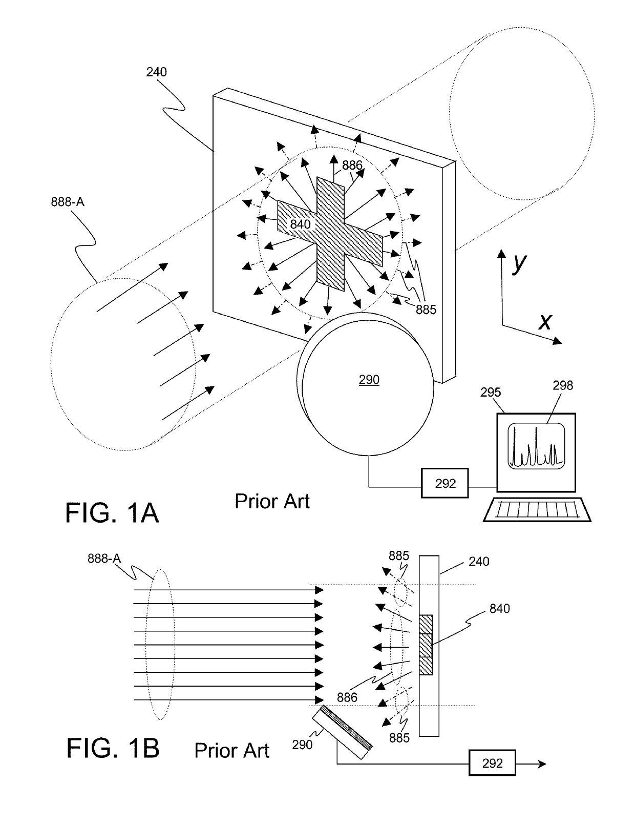
Such an illumination beam is not optimized to obtain high signal to noise ratio and / or high throughput using x-ray technique(s) on an object containing a single region of interest of arbitrary shape, or on a number of physically separated regions of similar or different shapes that may include periodic identical regions, such as semiconductor interconnects and through silicon vias (TSVs).
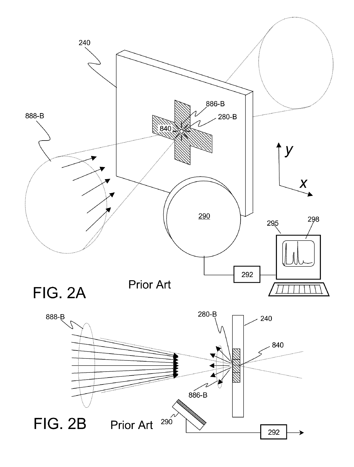
Attempts to increase the signal by increasing the integration time reduce the throughput, and in any case provide no information on anything but the illuminated spot.
Collecting data for the entire ROI will require additionally scanning the spot over the region, further reducing the throughput.

Method used


Image

  • X-ray techniques using structured illumination
  • X-ray techniques using structured illumination
  • X-ray techniques using structured illumination

Examples


Embodiment Construction

1. Basic Embodiment and Method

[0040]The invention disclosed herein relates to a method and apparatus for x-ray techniques using structured x-ray illumination for examining a designated property of an object.

[0041]FIGS. 3A and 3B illustrate the use of one embodiment of the invention for use with the object 240 as was illustrated in FIGS. 2A and 2B. The x-ray beam 888-C has a profile such that, at the object 240, the cross section of the x-ray beam 280-C converges to have the same size and shape as the ROI 840 of the object 240, represented in these figures by a cross-shaped region. Higher x-ray flux may therefore be used since the x-rays are distributed over a larger area, generating a larger signal, and yet, if the beam 280-C and the ROI 840 are well matched, x-ray signal(s) from the surrounding area of the ROI 840 will be minimized, improving the signal-to-noise ratio and / or measurement throughput.

1.1. Steps of a Method According to the Invention

[0042]An example of a method accordi...


PUM

PropertyMeasurementUnit
anglesaaaaaaaaaa
anglesaaaaaaaaaa
diameteraaaaaaaaaa

Abstract

This invention discloses a method and apparatus for x-ray techniques using structured x-ray illumination for examining material properties of an object. In particular, an object with one or more regions of interest (ROIs) having a particular shape, size, and pattern may be illuminated with an x-ray beam whose cross sectional beam profile corresponds to the shape, size and pattern of the ROIs, so that the x-rays of the beam primarily interact only with the ROIs. This allows a greater x-ray flux to be used, enhancing the signal from the ROI itself, while reducing unwanted signals from regions not in the ROI, improving signal-to-noise ratios and / or measurement throughput. This may be used with a number of x-ray measurement techniques, including x-ray fluorescence (XRF), x-ray diffraction (XRD), small angle x-ray scattering (SAXS), x-ray absorption fine-structure spectroscopy (XAFS), x-ray near edge absorption spectroscopy, and x-ray emission spectroscopy.

Description

CROSS-REFERENCE TO RELATED APPLICATIONS[0001]This Patent Application is a continuation-in-part of U.S. patent application Ser. No. 14 / 712,917, filed May 15, 2015 and entitled “X-RAY METHOD FOR THE MEASUREMENT, CHARACTERIZATION, AND ANALYSIS OF PERIODIC STRUCTURES”, which claims the benefit of U.S. Provisional Patent Application No. 61 / 993,792, filed May 15, 2014 and entitled “Method of Talbot-Effect Based X-ray Patterned Probe and Characterization (Metrology or Inspection) Apparatuses Using Such”, and is also a continuation-in-part of application Ser. No. 14 / 700,137, filed Apr. 29, 2015 and entitled “X-RAY INTERFEROMETRIC IMAGING SYSTEM”, which in turn claims the benefit of Provisional Patent Application No. 61 / 993,811, filed May 15, 2014 and entitled “Method of Talbot Effect based X-ray Imaging with High Image Contrast and Design of Apparatus Using Such”, all of which are incorporated herein by reference in their entirety; the present Application additionally claims the benefit of ...

Claims


Application Information

Patent Timeline
Patent Type & Authority Patents(United States)
IPC IPC(8): G01N23/20H01J35/08A61B6/00G01N23/201G21K1/02G01N23/223
CPCA61B6/4007A61B6/4291A61B6/484G01N23/223H01J35/08A61B6/508G21K1/02G01N23/20075G01N23/201G21K2207/005H01J2235/086H01J2235/1291G01N23/207
Inventor YUN, WENBINGLEWIS, SYLVIA JIA YUNKIRZ, JANOS
Owner SIGRAY INC
Learn More