
Electric motor and radiator fan module comprising an electric motor of this type

a technology of electric motors and radiator fans, which is applied in the direction of machines/engines, mechanical equipment, magnetic circuit shapes/forms/construction, etc., can solve the problems of requiring additional installation space, and achieve the effects of simple and cost-effective, simple shape and small installation spa

Active Publication Date: 2019-08-27
BROSE FAHRZEUGTEILE GMBH & CO KG HALLSTADT (DE)
View PDF14 Cites 0 Cited by
  • Summary
  • Abstract
  • Description
  • Claims
  • Application Information

AI Technical Summary

Benefits of technology

This solution provides a space-saving, cost-effective earth connection that simplifies the assembly process and offers greater design flexibility by decoupling the earth connection from the fastening mechanism, reducing the need for large steel spring clips.

Problems solved by technology

Because the steel spring clips are used to fasten the housing and the cover, they require additional installation space.

Method used


Image

  • Electric motor and radiator fan module comprising an electric motor of this type
  • Electric motor and radiator fan module comprising an electric motor of this type
  • Electric motor and radiator fan module comprising an electric motor of this type

Examples


first embodiment

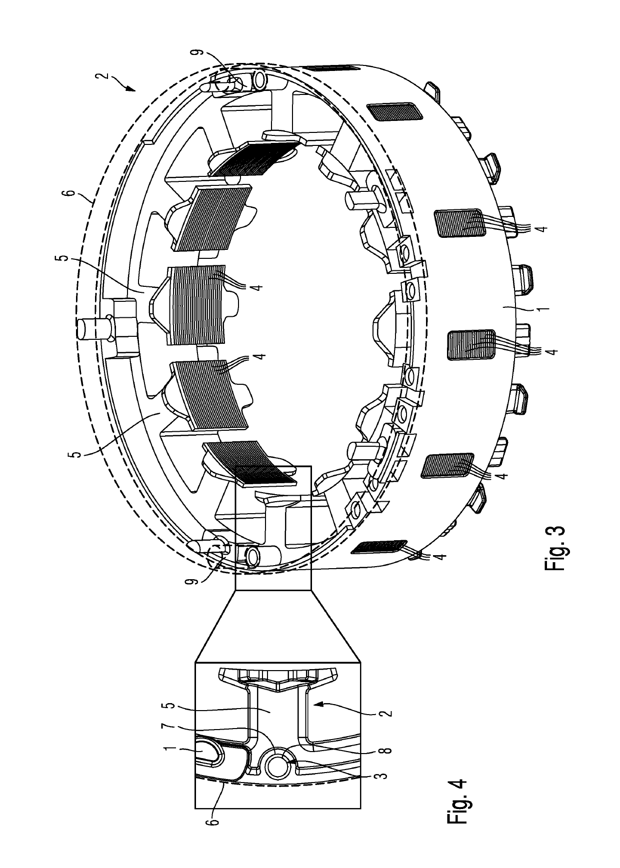
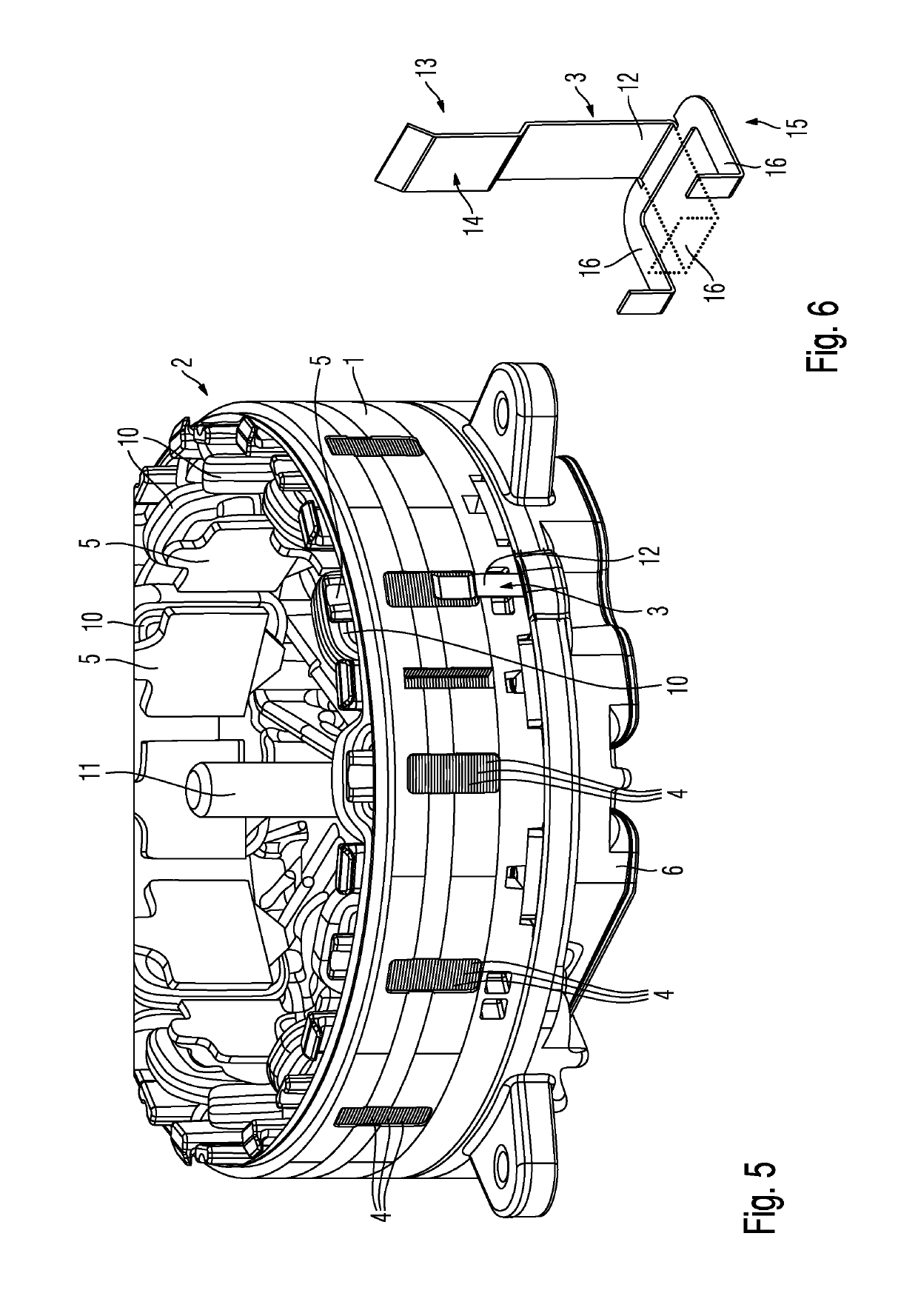
[0038]FIG. 1 shows a detail of a claimed electric motor 2 according to the invention. Furthermore, FIG. 2 is a perspective view of a connecting and contacting element 3 according to the invention for use in the electric motor 2 according to FIG. 1. Furthermore, FIG. 3 is another perspective view of the electric motor 2 according to FIG. 1 and FIG. 4 shows an enlarged detail of the electric motor 2 according to FIG. 3.

[0039]The electric motor 2 according to the invention comprises the stator 1, as shown in FIGS. 1, 3 and 4. The stator 1 comprises layered metal sheets 4, between each of which sheets 4 electrical insulation, e.g. an electrical insulation layer, is provided. The stator 1 further comprises a plurality of stator teeth 5, which are provided with coil windings (not shown), for providing for example a multi-phase, e.g. three-phase, rotating-field winding. The coil windings are not shown in FIGS. 1, 3 and 4 for reasons of clarity.

[0040]In the embodiment in FIGS. 1, 3 and 4, p...

third embodiment

[0056]Furthermore, FIG. 9 shows an electric motor 2 according to the invention. FIG. 9 is a perspective view of a motor support 6 of the electric motor 2 according to the invention and a stator 1. In FIG. 9, the stator 1 is indicated in a purely schematic and highly simplified manner by a dashed line.

[0057]The third embodiment of the electric motor 2 has substantially the same design as the electric motors in the first and second embodiments of the invention, and therefore, in this respect, reference is made to the description thereof with regard to FIG. 1-8 in order to avoid unnecessary repetitions.

[0058]Furthermore, the third embodiment of the electric motor 2 differs from the first embodiment and the second embodiment in that the motor support 6 comprises a connecting and contacting element 3 in the form of a pin 17 made of an electrically conductive material, which is for example inserted or embedded in said motor support. In order to establish an earth connection, said pin 17 i...


PUM


Abstract

The present invention relates to an electric motor, the electric motor including: a stator, which is composed of layered metal sheets, a motor support made of an electrically conductive material, a cable connection comprising an earth line cable, and at least one connecting and contacting element made of an electrically conductive material, wherein the connecting and contacting element is configured and arranged on the electric motor such that it provides an earth connection between the stator and the motor support or between the stator and the earth line cable of the cable connection, and wherein the stator and the motor support are fastened to one another independently of the connecting and contacting element.

Description

FIELD[0001]The present invention relates to an electric motor and a radiator fan module comprising an electric motor of this type, in particular a radiator fan module for a motor vehicle.TECHNICAL BACKGROUND[0002]In existing electric motors, discharge occurs via an earth connection of the wound stator of said electric motors to the motor support of said electric motors by means of screws, in order to provide the electric motor with the required electromagnetic compatibility (EMC).[0003]Furthermore, DE 10 2012 222683 A1 discloses an electric motor comprising a housing which is closed by means of a cover and comprises a connector part held between the housing and the cover for electrically contacting the electric motor. The housing is in this case manufactured from steel, the connector part from plastics material and the cover from an electrically conductive material. In this case, a plurality of steel spring clips are arranged so as to be distributed over the periphery of the electri...

Claims


Application Information

Patent Timeline
Patent Type & Authority Patents(United States)
IPC IPC(8): H02K1/04F01P5/04H02K11/40H02K5/22H02K1/18H02K7/14H02K5/06
CPCH02K11/40H02K5/225H02K5/06F01P5/04F01P2005/046H02K1/04H02K1/185H02K7/14H02K2203/15
Inventor SCHOELE, RAINERPFISTER, MARTINROHM, FRANZISKALUDWIG, KEVINWINHEIM, GEORG
Owner BROSE FAHRZEUGTEILE GMBH & CO KG HALLSTADT (DE)
Learn More