
Optical image anti-shake device with yoke

an anti-shake device and optical image technology, applied in the field of optical image anti-shake devices, can solve the problems of affecting the operation of the optical image anti-shake mechanism, the casing cannot prevent the magnet from attracting an external magnetically permeable component, and the anti-shake magnet cannot be disclosed. , to achieve the effect of enhancing a magnetic force, preventing external electromagnetic interference, and high magnetic retentivity

Active Publication Date: 2019-08-27
TDK TAIWAN
View PDF3 Cites 1 Cited by
  • Summary
  • Abstract
  • Description
  • Claims
  • Application Information

AI Technical Summary

Benefits of technology

[0011]In view of the aforesaid drawbacks of the prior art, there is a need for an optical image anti-shake device capable of converging magnetic lines of force and precluding external electromagnetic interference. The present invention provides an optical image anti-shake device with a yoke. The yoke has high magnetic retentivity and is capable of enhancing a magnetic force and precluding external electromagnetic interference.

Problems solved by technology

Although Japan Published Patent Application 2011-128583 discloses preventing the magnetic lines of force of the autofocus magnet from dispersing but does not disclose protecting an anti-shake magnet against the interference from an external magnetically permeable component.
As a result, Japan Published Patent Application 2011-128583 has a drawback as follows: if a magnetically permeable component is disposed outside the lens-unit driving device, it will attract the anti-shake magnet and thereby affect the operation of the optical image anti-shake mechanism.
However, Japan Published Patent Application 2012-113230 has a drawback, that is, if the internal magnet is located at an active portion, the casing cannot prevent the magnet from attracting an external magnetically permeable component.

Method used


Image

  • Optical image anti-shake device with yoke
  • Optical image anti-shake device with yoke
  • Optical image anti-shake device with yoke

Examples


Embodiment Construction

[0026]The present invention is hereunder illustrated with embodiments and drawings and described below. The drawings and the description below are further provided with reference numerals. The verb “comprise” used in the description below is syntactically open and thereby should be interpreted to mean “includes, but is not limited to.” Persons skilled in the art understand that it is not uncommon for a single component / product to have different names, for example, “lens holder” and “lens container.” Hence, all components / products equivalent to the ones mentioned herein in terms of technical field and function should be interpreted to fall within the scope of the present invention.

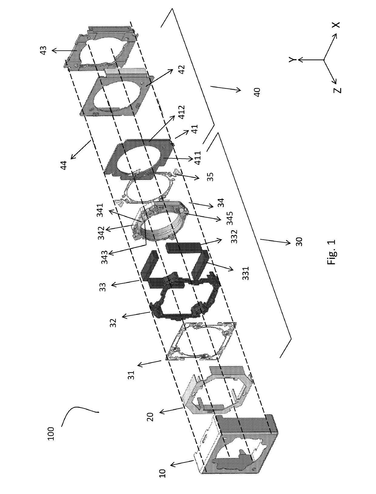
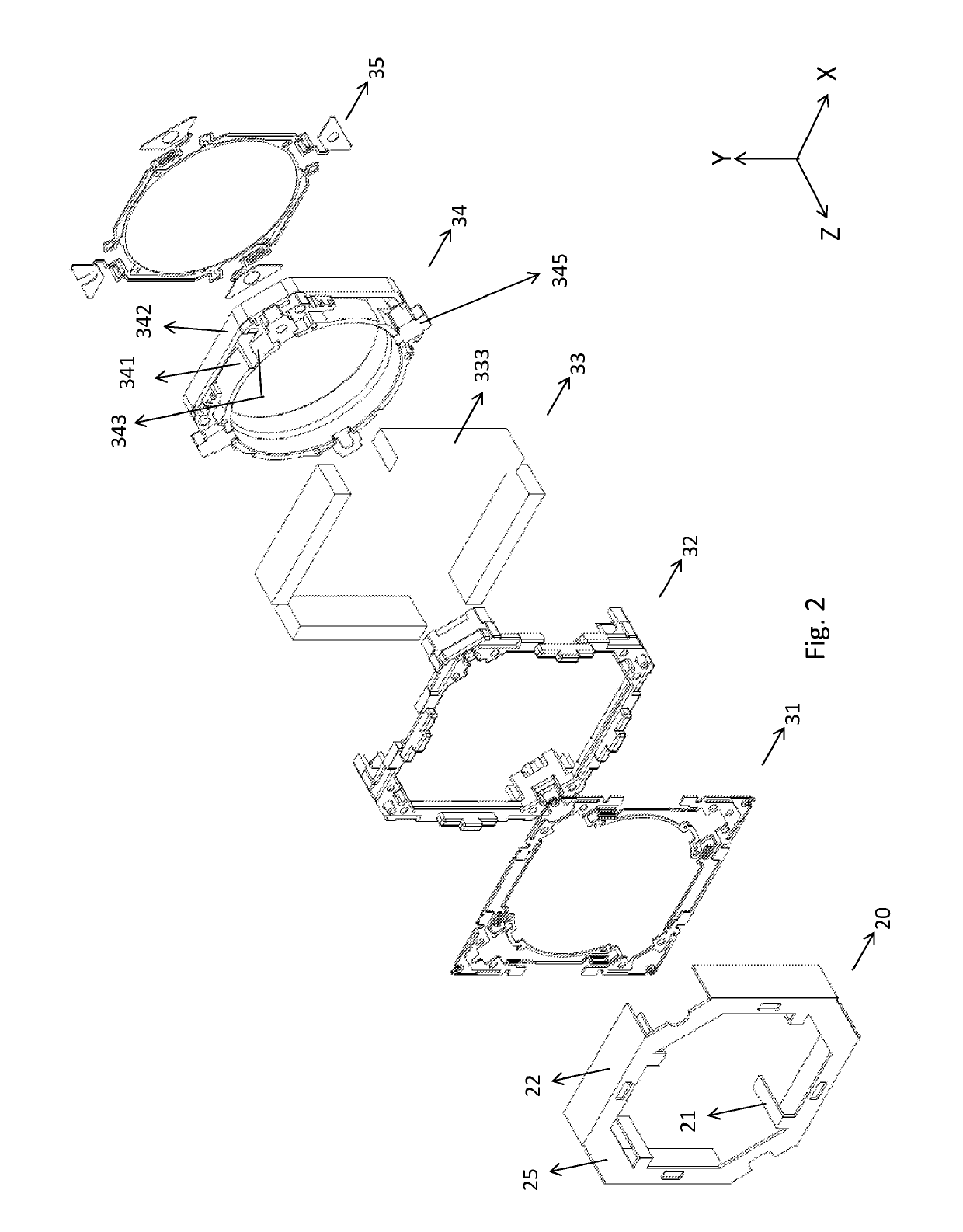
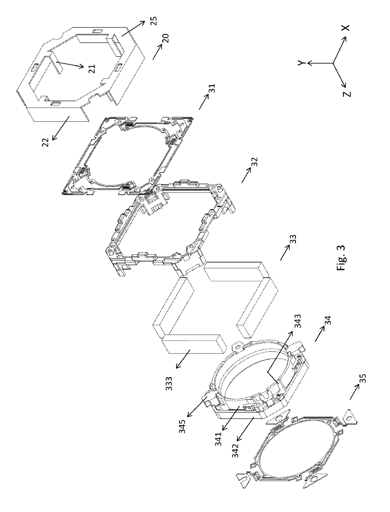
[0027]Referring to FIG. 1, there is shown an exploded view of an optical image anti-shake device 100 according to an embodiment of the present invention, with reference to an X-axis, a Y-axis and a Z-axis. In this embodiment, the optical image anti-shake device 100 comprises a casing 10, an active portion 3...


PUM


Abstract

An optical image anti-shake device with a yoke is provided. The optical image anti-shake device includes: a casing having a first aperture; a fixing portion having a bottom plate, the bottom plate having a second aperture corresponding in position to the first aperture; and an active portion enclosed by the casing and resiliently clamped between the casing and the bottom plate by the fixing portion, the active portion including: a correcting module for correcting, with a magnetic force, a blur of images caused by a shake of the optical image anti-shake device; a frame having a receiving space; a lens holder disposed in the receiving space of the frame; a lens unit corresponding in position to the first aperture and the second aperture, the lens unit being carried by the lens holder and having an image-capturing optical axis; and a yoke fixed to the frame.

Description

RELATED APPLICATIONS[0001]This application claims priority to Taiwan Application Serial Number 104112337, filed on Apr. 17, 2015, which is incorporated by reference herein in its entirety.BACKGROUND OF THE INVENTION[0002]Field of the Invention[0003]The present invention relates to optical image anti-shake devices and, more particularly, to an optical image anti-shake device for use with cameras and mobile devices.[0004]Description of the Prior Art[0005]One of the most important challenges facing by persons skilled in the art is to reduce or even eliminate the effect of a shaking camera positioned at a handheld device or a moving carrier (such as an automobile or a flight vehicle) upon pictures of formed images in the course from picture-taking to image-forming.[0006]Optical image anti-shake technique, which is rapidly developing, is regarded as a potential leader of image anti-shake techniques in the years to come. Unlike a digital image anti-shake mechanism, the optical image anti-...

Claims


Application Information

Patent Timeline
Patent Type & Authority Patents(United States)
IPC IPC(8): G02B7/02H04N5/232G02B27/64H04N5/225
CPCG02B7/08G02B27/646H04N23/54H04N23/55G02B7/023H04N23/687
Inventor HU, CHAO-CHANGCHEN, SHU-SHANCHEN, YI-HO
Owner TDK TAIWAN
Learn More