Hose carrier

a technology of hoses and conduits, applied in the direction of conveyor parts, transportation and packaging, thin material processing, etc., can solve the problem of not having a specific solution for the problem of moving hoses and other conduits over ground or structural surfaces

Active Publication Date: 2019-08-20
MCDONALD DUSTIN
View PDF7 Cites 2 Cited by
  • Summary
  • Abstract
  • Description
  • Claims
  • Application Information

AI Technical Summary

Benefits of technology

The patent text describes an apparatus for providing roller support for hoses or conduits. It consists of a frame made up of two separate half-cylinders that are joined along a split line to form a cylinder. The frame can be opened and closed manually, and has roller appendages that provide support for hoses or conduits of different diameters. The rollers are made of a high-density polymer material and the hinge mechanism is a thin plastic strip or fabric heat-welded or glued to the frame elements. The closed frame elements are securely locked together using a latch mechanism. The technical effects of this apparatus are that it provides a convenient and effective way to support and protect hoses or conduits, and can be adjusted to different diameters without having to modify the frame.

Problems solved by technology

There exist, at the time of filing the present application, no specific solution for the problem of moving hoses and other conduits over ground or structural surfaces other than just picking up the hose, or a portion of the hose and carrying it to a different location.

Method used


Image

  • Hose carrier
  • Hose carrier
  • Hose carrier

Examples


Embodiment Construction

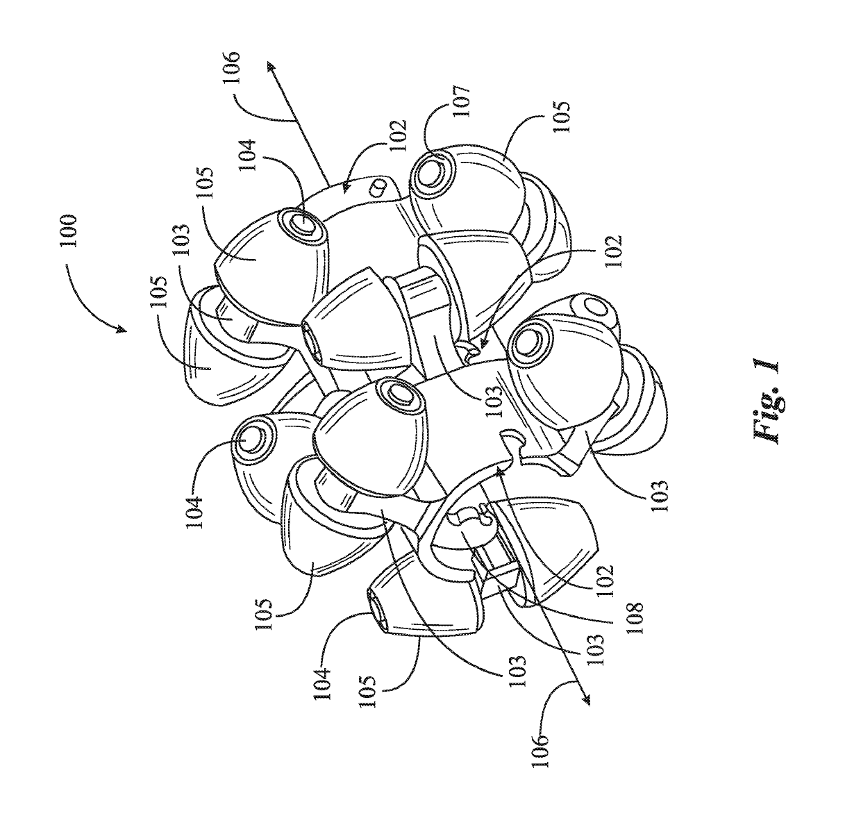
[0025]FIG. 1 is a perspective view of a roller assembly 100 providing roller support for a hose or conduit in one embodiment of the invention, a plurality of such assemblies, attached to and spaced apart along a length of a hose or conduit, enabling the hose or conduit to move easily over any supporting surface, or around or over any restraining obstacle. Roller assembly 100 comprises, in this implementation, three connected bases 102, connected in a manner that they may entrain a hose along an axis direction 106, each base 102 having three appendages 103, each appendage 103 providing a bore mounting an axle rod 104, with each axle rod 104 providing a mount for two rollers 105, one on each side of the appendage 103. This arrangement provides a total of eighteen rollers, facing in different directions, such that a plurality of rollers will be in contact with any supporting surface or obstacle at any point in time.

[0026]In FIG. 1 not every instance of every element is provided with an...


PUM


Abstract

An apparatus comprising a cylindrical split frame, hinged on one side with a latch on the other side, a plurality of roller appendages extending outward from the frame, presenting axle rods having rollers. The apparatus clamps over a hose or a conduit and carries the hose or conduit on the rollers.

Description

CROSS-REFERENCE TO RELATED APPLICATIONS[0001]The present application claims priority to co-pending application Ser. No. 15 / 784,115, filed Oct. 17, 2017, which claims priority to a provisional patent application, 62 / 414,350, filed Oct. 28, 2016, and all disclosure of the parent applications is incorporated herein at least by reference.BACKGROUND OF THE INVENTION1. Field of the Invention[0002]The present invention is the technical area of mechanical devices for reducing friction; and pertains more particularly to a device for reducing friction and drag for hoses and other conduits, when moving such conduits over supporting surfaces.2. Description of Related Art[0003]It is well known in the art that there are many pressing needs for moving and relocating hoses and other conduits in many different circumstances. Hoses in gardening and landscaping applications, for example, typically must be connected at a head end to a hose spike, or other source of water, and must be moved to a point o...

Claims


Application Information

Patent Timeline
Patent Type & Authority Patents(United States)
IPC IPC(8): F16L3/00A62C33/04F16L3/18B65G39/12B65H75/40
CPCA62C33/04F16L3/18B65G39/12B65H2701/33B65H75/403B65H57/14
Inventor MCDONALD, DUSTIN
Owner MCDONALD DUSTIN
Why Eureka
Try Eureka