
Method and system for inserting an insert element into a panel product, the panel product produced thereby and method and system for performing a tensile test on the inserted insert element

a technology of insert elements and panel products, which is applied in the directions of transportation and packaging, mechanical equipment, and fastening means, etc., can solve the problems of unusability of panel products, predetermined load-bearing capacity, and laborious procedures, so as to maximize free space and volume of panel products, reduce the weight of panel products, and ensure the effect of rigidity

Inactive Publication Date: 2019-08-13
RUAG SCHWEIZ AG
View PDF18 Cites 2 Cited by
  • Summary
  • Abstract
  • Description
  • Claims
  • Application Information

AI Technical Summary

Benefits of technology

The patent text describes the production of light construction panels made of framework elements or honeycomb cores. These panels are designed to be strong and allow for a large amount of empty space between the framework elements or honeycomb cores. A cover layer is added to each side of the panels to provide additional strength and protection. The arrangement of the framework elements or honeycomb cores ensures the panels are stiff and have the necessary strength while minimizing weight. This construction method allows for the creation of strong and lightweight panels with a lot of empty space between them.

Problems solved by technology

This procedure is intensive in work, time, and costs, and as a result can only be repeated to a limited extent in the scope of typical reproducibility of a manually executed process, and is subject to a risk that a load-bearing capacity of an anchor of the insert element in the panel product does not achieve a predetermined load-bearing capacity.
In an unfavorable case, a panel product will become unusable due to an insert element inserted with insufficient load-bearing capacity.

Method used


Image

  • Method and system for inserting an insert element into a panel product, the panel product produced thereby and method and system for performing a tensile test on the inserted insert element
  • Method and system for inserting an insert element into a panel product, the panel product produced thereby and method and system for performing a tensile test on the inserted insert element
  • Method and system for inserting an insert element into a panel product, the panel product produced thereby and method and system for performing a tensile test on the inserted insert element

Examples


first embodiment

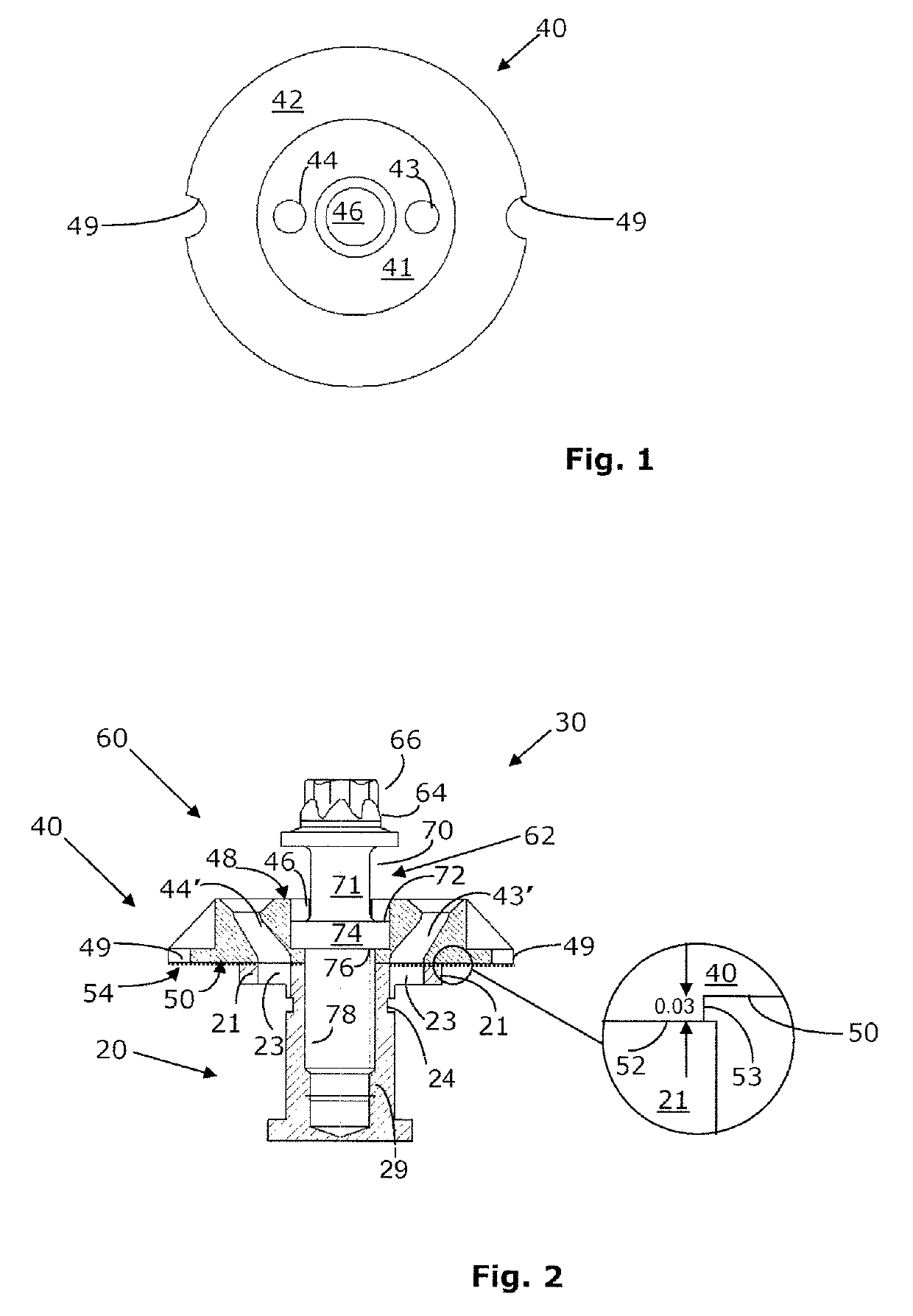
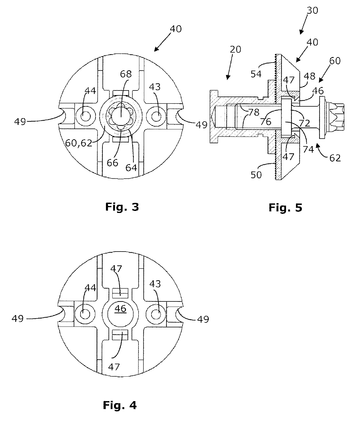
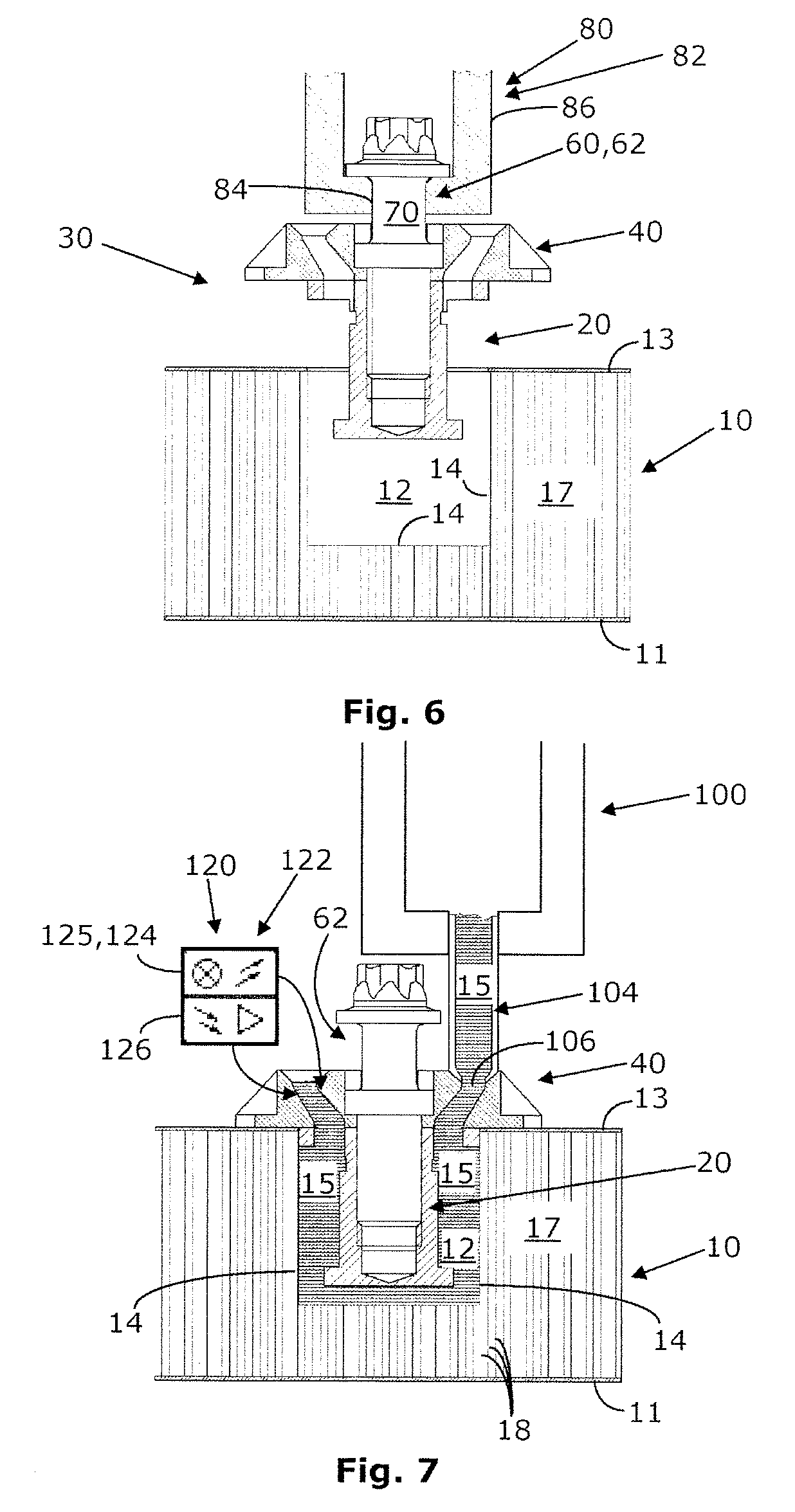
[0085]In the first embodiment, a method and a system for producing a panel product device are provided. The method and the system require, as the starting point, a panel precursor product 11 having at least one recess 12, which is implemented in a panel surface 13, having a delimitation in relation to a base material 17 (see FIG. 6) and at least one insert element 20, which is provided to be inserted into the recess 12, and which is preassembled together with a cover and positioning unit 40 by means of a connecting unit 60 to form a composite element (see FIGS. 2 and 5). The method and system according to the invention for inserting insert elements 20 into recesses 12 of the panel precursor product 11 replace the previously practiced manual insertion and embedding in foam of insert elements 20 in the recesses 12.

[0086]The system comprises means for automated insertion of the insert element 20 into the recess 12 of the panel precursor product 11 (see FIG. 6) and means for automated f...

second embodiment

[0115]The cover and positioning unit 140 has on its lower side 150 channel extensions 143″ and 144″, which are implemented around openings implemented thereon (decanting opening 143 and outlet opening 144), as can be seen in the two corresponding detail images of FIG. 10. Thus, the decanting channel extension 143″, which encloses the outlet of the decanting channel 143′ is implemented around the decanting opening 143 of the unit 140 on the lower side 150, this extension protruding downward from the lower side 150 in FIG. 10, i.e., in the direction toward the insert element 20 to be applied from the lower side 150. When the insert element 20 is preinstalled on the lower side 150 of the insert element 140, the channel extension 143″ protrudes into the corresponding through hole 23 in the upper flange 21. Correspondingly, an outlet channel extension 144″ is implemented around the outlet opening 144 on the lower side 150 of the unit 140, this extension extending the outlet channel 144′ ...


PUM

PropertyMeasurementUnit
heightaaaaaaaaaa
heightaaaaaaaaaa
heightaaaaaaaaaa

Abstract

In a method and a system for producing a panel product device, in which a panel pre-product is provided, comprising at least one recess formed in a panel surface and having a delimitation, and at least one insert element is provided, intended for anchoring in at least one of the recesses, the system comprises automated means for inserting the insert element into the recess in the panel pre-product, and automated means for filling an intermediate space between the insert element and the delimitation of the recess with a curable or curing filling fluid. In a method and a system for testing the loading resistance of the connection between the insert element and the recess in the panel surface of the panel pre-product, a variable tensile testing force is applied in an automated manner to the insert element up to a predetermined tensile testing force. Finally, a set of auxiliary assembly tools for use in the production method or system is provided, comprising a covering and positioning device for inserting and positioning the insert element in the recess and a connecting device for releasably connecting the insert element to the covering and positioning device.

Description

CROSS REFERENCE TO RELATED APPLICATIONS[0001]This application is entitled to the benefit of and incorporates by reference essential subject matter disclosed in International Patent Application No. PCT / EP2012 / 070549 filed Oct. 17, 2012.BACKGROUND[0002]The present invention relates to a method and a system for inserting an insert element into a panel product, a panel product or panel product device produced using the method or the system, and an aircraft or spacecraft in which the panel product is installed.SUMMARY[0003]The relevant panel products are typically produced in light construction. In this case, a base material of the panel product comprises, in a first embodiment, a plurality of framework elements in an arrangement spaced apart as far as possible from one another or, in a second embodiment, a plurality of honeycomb cores having honeycomb core walls, wherein the honeycomb cores are generally implemented as hexagonal in a cross section parallel to a surface of the base mater...

Claims


Application Information

Patent Timeline
Patent Type & Authority Patents(United States)
IPC IPC(8): B64C1/06F16B11/00B32B37/14F16B13/14F16B5/01B32B37/12B29C65/54B29C65/48B29C65/00
CPCB29C65/48F16B13/141B29C65/542B29C66/7254F16B11/006B32B37/12B32B37/142B64C1/066F16B5/01B29C66/72525B29C31/041
Inventor KÖGL, STEFAN
Owner RUAG SCHWEIZ AG
Learn More