Passive ductwork intumescent fire damper

a technology of intumescent fire damper and ductwork, which is applied in the direction of ducting arrangement, lighting and heating apparatus, heating types, etc., can solve the problems of inconvenient use, inconvenient use, and inconvenient use of dampers, etc., to achieve simple and flexible design, useful in small ductwork and ventilation applications

Active Publication Date: 2019-07-30
SUPERPOSED ASSOC LLC
View PDF81 Cites 3 Cited by
  • Summary
  • Abstract
  • Description
  • Claims
  • Application Information

AI Technical Summary

Benefits of technology

[0007]A primary object of the present invention is to provide a passive intumescent fire damper with a simple and flexible design and useful in small ductwork and ventilation applications.
[0009]Another primary object of the present invention is to provide a passive ductwork intumescent fire damper simple in construction, inexpensive and easy to install and use.

Problems solved by technology

In some applications, these dampers cannot be used due to products or byproducts in the air stream which will cause build up and create a hazard of blockage or possibly negatively impair the proper operation of the damper.
Such dampers are usually not suitable for use in small ductwork including kitchen exhaust, dryer exhaust, bathroom ventilation and any other ductwork which may require material collection such as in a shop having substantial dust of material build up.
Such devices while useful for certain applications are complex, expensive and do not readily lend themselves to use in ductwork of smaller applications such as a kitchen exhaust, dryer exhaust or the like.
However, these fire dampers are complex and expensive to manufacture.
These devices while useful in certain situations have various shortcomings including their complex nature, their expense to manufacture and their inability to work well in small ductwork or ventilation systems.

Method used


Image

  • Passive ductwork intumescent fire damper
  • Passive ductwork intumescent fire damper
  • Passive ductwork intumescent fire damper

Examples


Embodiment Construction

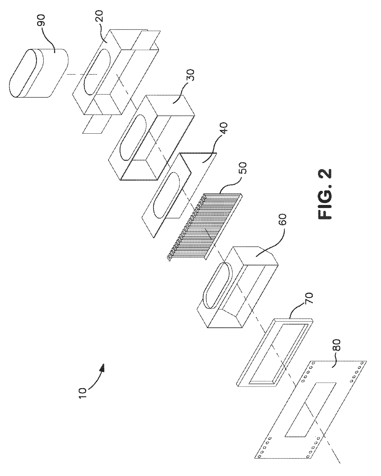
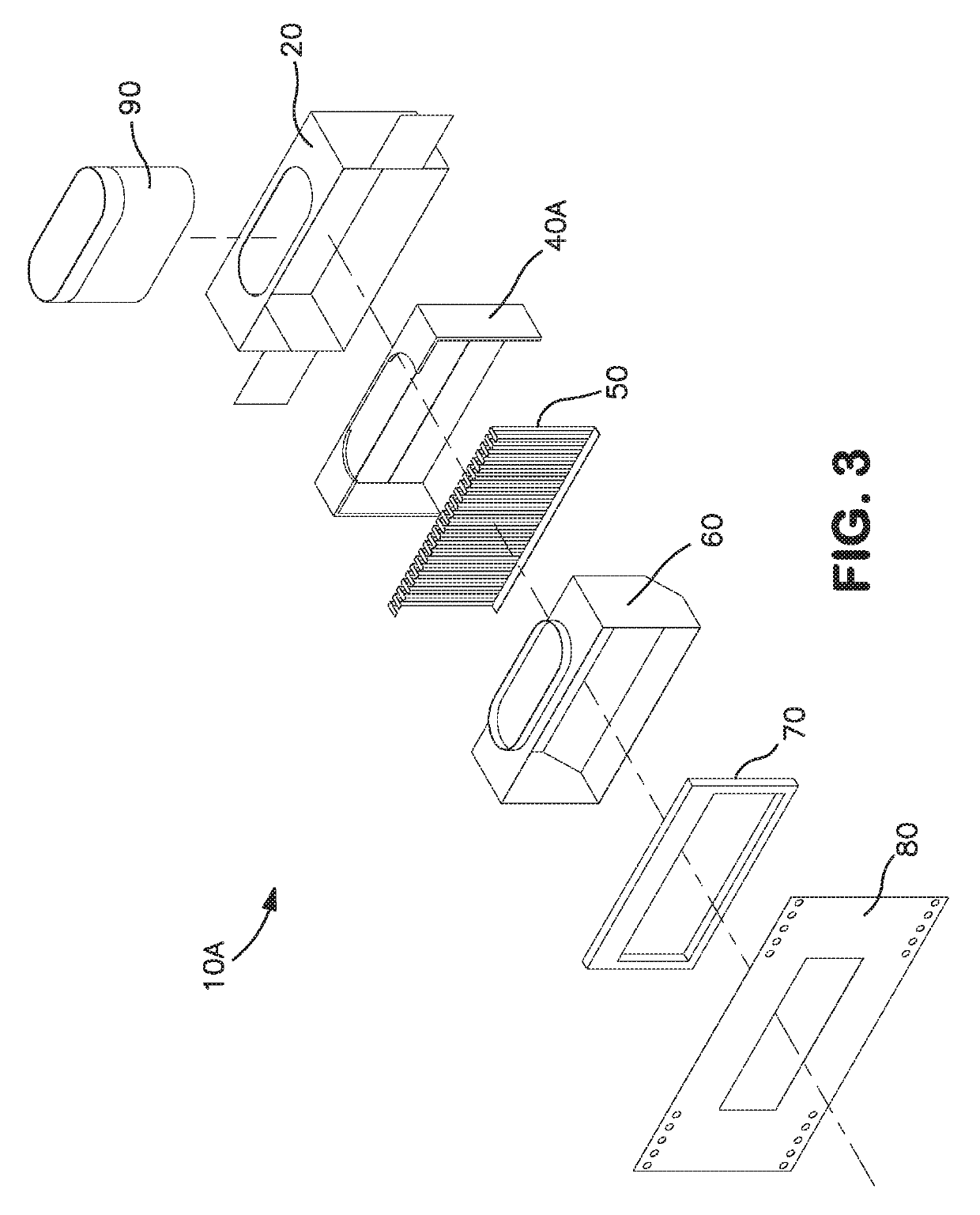
[0031]The passive ductwork intumescent fire damper invention is illustrated in FIGS. 1-13. There are two embodiments disclosed as seen, for example, in FIGS. 2 and 3. The embodiments are similar except that the embodiment in FIG. 3 does not use a ceramic lining and the shape of the intumescent in FIGS. 2 and 3 are different. Otherwise, the embodiments of FIGS. 2 and 3 are substantially the same.

[0032]As best seen, for example, in FIG. 2, a fire damper 10 comprises a sheet metal box 20; a ceramic sheet lining 30; an L-shaped intumescent 40; a sheet metal comb 50; a plastic liner 60; a sheet metal comb catch 70; and a sheet metal escutcheon 80. Attached to the fire damper is a sheet metal male sleeve 90 which fits into the sheet metal box 20 and is connected to a duct (not shown). The fire damper 10 shown for purposes of illustration is rectangular. However, it is understood that the invention is useful with other shape fire dampers. It is further understood that the other components ...


PUM


Abstract

A passive ductwork intumescent fire damper is disclosed having a sheet metal box; an intumescent; a sheet metal comb; a plastic liner; a sheet metal comb catch; and a sheet metal escutcheon. The fire damper is particularly useful in a structural wall ducted horizontally such as a side wall range hood installation.

Description

RELATED APPLICATION[0001]This application claims benefit of U.S. Provisional Application Ser. No. 62 / 357,211, filed Jun. 30, 2016, entitled “Passive Ductwork Intumescent Fire Damper,” which application is incorporated herein by reference in its entirety.FIELD OF THE INVENTION[0002]The present invention relates to a passive ductwork intumescent fire damper. More particularly, the invention relates to a fire damper for use in a structural wall ducted horizontally such as a side wall range hood installation.BACKGROUND OF THE INVENTION[0003]Fire dampers are known in the art. For example, fire dampers and ceiling radiation dampers (collectively and broadly referred herein to as “fire damper”) which are “dynamic” and “standard” are known and require periodic testing according to some code requirements to ensure their proper operation. In some applications, these dampers cannot be used due to products or byproducts in the air stream which will cause build up and create a hazard of blockage...

Claims


Application Information

Patent Timeline
Patent Type & Authority Patents(United States)
IPC IPC(8): A62C2/06F24F11/35F16L5/04F24F13/08F24F13/02A62C3/00E04B1/94
CPCA62C2/065E04B1/947F16L5/04F24F13/0263F24F13/08F24F2221/30A62C2/06A62C3/006F24F11/35
Inventor KING, JR., JACK F.
Owner SUPERPOSED ASSOC LLC
Why Eureka
Try Eureka