
Intraoperative image registration by means of reference markers

a technology of reference markers and image data, applied in image enhancement, instruments, applications, etc., can solve the problems of inability to rectify tomographic image data, and inability to accurately superimpose image data, so as to achieve the effect of optimizing the accuracy of the superposition of image data

Active Publication Date: 2019-07-30
INTERSECT ENT GMBH
View PDF11 Cites 3 Cited by
  • Summary
  • Abstract
  • Description
  • Claims
  • Application Information

AI Technical Summary

Benefits of technology

The patent is about a method for improving the accuracy and precision of surgical procedures using computed tomography (CT) images and x-ray fluoroscopy images. The CT images are created before surgery using a scanner, while the fluoroscopy images are recorded during surgery using a C-arm. These images can be compared to each other to help medical professionals better plan and carry out the surgery. The method also involves using a field generator to generate a medical image. The generator has a frame-shaped design that can be placed on an operating table to avoid pressure points on the patient. The technical effect of the patent is to improve the accuracy and precision of surgery procedures by combining the benefits of CT images and fluoroscopy images with the use of a field generator.

Problems solved by technology

Instead, tomographic image data are disadvantageous in relation to F / V image data in that they generally do not depict the recorded regions true to scale but rather in a distorted manner.
Such known methods for rectifying tomographic image data are disadvantageous in that they often produce erroneous results.
Furthermore, the different image data are often created at different times, and so e.g. acute swelling, bruising, etc. can lead to errors when rectifying the tomographic image data.

Method used


Image

  • Intraoperative image registration by means of reference markers
  • Intraoperative image registration by means of reference markers
  • Intraoperative image registration by means of reference markers

Examples


first embodiment

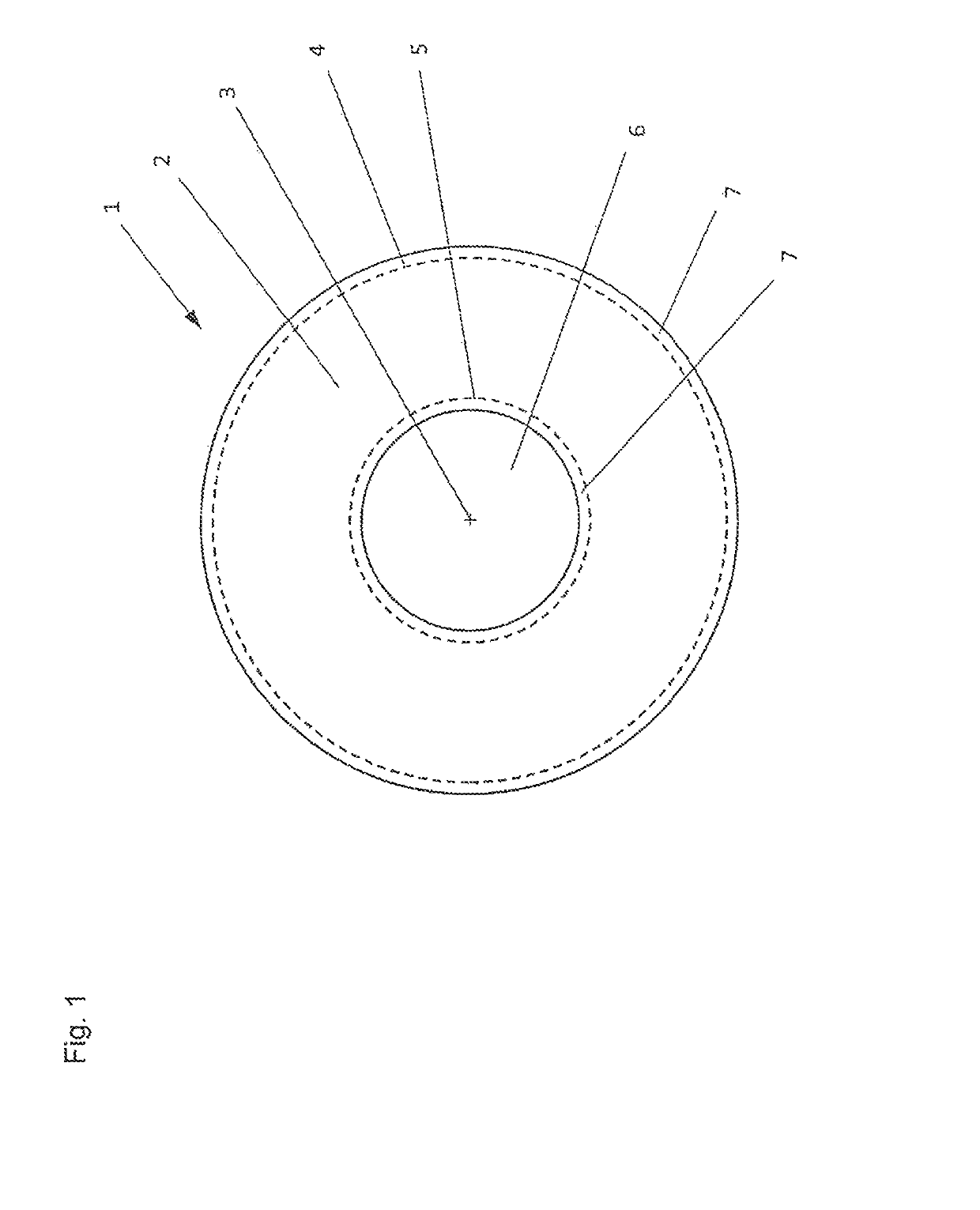
[0055]a first reference body 1 according to the invention, schematically depicted in FIG. 1, comprises a ring-shaped main body 2, depicted using dashed lines, with a center point 3, an outer circumference 4 and a smaller inner circumference 5. A circular through-hole 6 through the main body 2 is delimited by the inner circumference 5, which through-hole is concentric with the main body 2. The main body 2 is preferably formed from a material which exhibits poor transmissivity of x-ray beams. In particular, metals, such as e.g. lead, are suitable to this end. It is not possible to identify in this view that the two surfaces of the main body 2 have a flat embodiment. In alternative embodiments, one or both surfaces can also have a convex arching, which extends radially toward the center 3.

[0056]The main body 2 is completely encapsulated by a cover layer 7 made of material that differs from the material of the main body 2. In this first exemplary embodiment, the cover layer 7 is arrange...

second embodiment

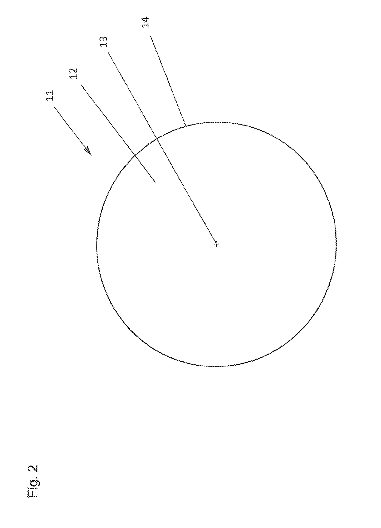
[0057]a first reference body 11 according to the invention, depicted in FIG. 2, has a circular main body 12 with a center point 13 and an external circumference 14. There is no cover layer in the imaged second exemplary embodiment; however, it can be added when necessary.

third embodiment

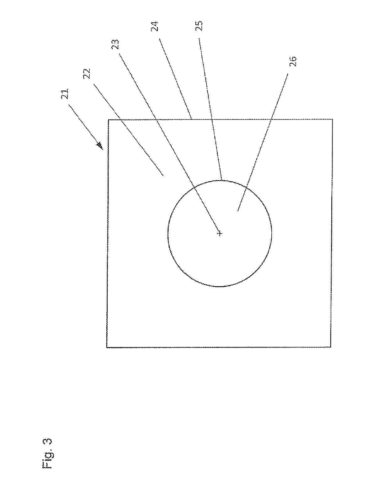
[0058]FIG. 3 shows a first reference body 21 according to the invention. The first reference body 21 has a square main body 22 with a center point 23, an external circumference 24 and a circular through-hole 26, which is concentric with the main body 22. The through-hole 26 is delimited toward the outside in the radial direction by way of an internal circumference 25 of the main body 22.

[0059]In the case where the main body 2, 12, 22 has a sufficient solidity such that it does not permanently deform under intended usage conditions, the possible top layer 7 can be formed from an elastic material, for example in order to protect the main body 2, 12, 22 from external influences such as impacts. In particular, rubbery-elastic substances, silicones, etc. come into question here. Preferably, the cover layer can also be embodied as an elastic or rigid envelope, into which the main body 2, 12, 22 is insertable.

[0060]To the extent that the cover layer 7 has a significantly better transmissiv...


PUM


Abstract

A method for incorporating tomographically obtained image data from a patient into a system for surgical planning and / or intraoperative navigation involves tomographic image data or image data obtained by X-ray recordings from at least one defined body area of the patient by at least one first recording appliance, wherein a first reference body having at least one surface is arranged on the patient and is recorded by the first recording appliance at the same time. The recorded image data representing the first reference body are compared with known geometric data from the first reference body in order to obtain distortion information. The recorded image data are equalized by a computation unit based on the distortion information to obtain equalized image data which have further image data from the same body area superimposed to obtain superimposed image data that is presented on a display.

Description

CROSS REFERENCE TO RELATED APPLICATIONS[0001]This application is the U.S. National Stage of International Application Number PCT / EP2014 / 060172 filed on May 16, 2014 which application claims priority under 35 USC § 119 to German Patent Application No. 10 2013 209 158.3 filed on May 16, 2013, which applications are hereby incorporated by reference in their entirety.TECHNICAL FIELD[0002]The invention relates to a method for including image data obtained by means of an imaging method, in particular a tomographic method, in a system for operation planning and / or for intraoperative navigation, wherein the image data is initially obtained, or was obtained previously, by means of imaging methods such as x-ray and / or computed tomography. The invention also relates to a reference body, an electromagnetic field generator and a medical system, in particular for use in such a method in each case.BACKGROUND OF THE INVENTION[0003]The use of image data, generally available in digital form, of a pat...

Claims


Application Information

Patent Timeline
Patent Type & Authority Patents(United States)
IPC IPC(8): A61B5/06A61B17/00A61B34/10A61B34/20A61B5/055G06T7/73A61B6/00A61B90/00G06T11/00
CPCA61B5/066A61B6/5235A61B6/547A61B6/584A61B6/589A61B90/39G06T7/75G06T11/00A61B6/487G06T2207/30204A61B5/055A61B2017/0092A61B2034/107A61B2034/2051A61B2034/2065A61B2090/364A61B2090/3762A61B2090/3966A61B2090/3983A61B2560/0228A61B2576/00G06T2200/04G06T2207/10072G06T2207/10121G06T2207/20221G06T2207/30012A61B6/583G16H30/40G06T5/80
Inventor KRUGER, TIMOMUCHA, DIRK
Owner INTERSECT ENT GMBH
Learn More