
Machine tool thermal displacement and magnification correction adjustment

a technology of magnification correction and machine tool, applied in the field of machine tools, can solve the problems of difficult to accurately analyze all causes and make thermal corrections with high accuracy, and the accuracy of thermal displacement is extremely difficult to achiev

Active Publication Date: 2019-07-16
YAMAZAKI MAZAK KK
View PDF26 Cites 4 Cited by
  • Summary
  • Abstract
  • Description
  • Claims
  • Application Information

AI Technical Summary

Benefits of technology

The patent is about a system that helps workers estimate the temperature of their environment. Sometimes, the results may not be accurate, so the system offers suggestions on how to adjust the measurements. This setup makes it easier for workers to manually adjust the measurements and ensures that the results are correct.

Problems solved by technology

A thermal expansion of each of members constituting a machine tool due to heat generated by operating the machine tool and heat from the surroundings of the machine tool is a significant cause that brings the relationship in position between a blade edge of a tool and a machining workpiece to a misaligned state.
As a result, the machining accuracy may be deteriorated.
Further, it is extremely difficult to accurately analyze all causes and make thermal corrections with high accuracy.
In particular, a temperature variation due to external causes existing outside the machine tool is unanalyzable in principle, and thus, the thermal displacement is extremely difficult to correct with accuracy.

Method used


Image

  • Machine tool thermal displacement and magnification correction adjustment
  • Machine tool thermal displacement and magnification correction adjustment
  • Machine tool thermal displacement and magnification correction adjustment

Examples


example 1

PRACTICE EXAMPLE 1

Correction Magnification Setting Support Screen

[0064]The correction magnification setting support screen 400 is illustrated in FIG. 8 as first embodiment. The correction magnification setting support screen 400 includes a graph display section 410, a machining state data extraction section 430, the machining state data input / display section 450, and a correction magnification adjustment operation section (a correction magnification adjustment operator) 470.

[0065]The graph display section 410 includes the machining size graph display section 412 and the temperature graph display section 421. The machining size graph display section 412 is displayed in an upper portion of the graph display section 410 and the temperature graph display section 421 is displayed in a lower portion of the graph display section 410.

[0066]The machining state data extraction section 430 includes a data extraction mode switch section 432, the selection data derivation input section 433, a co...

example 2

PRACTICE EXAMPLE 2

[0136]Practice example 2 in relation to the correction magnification setting support function will be described focusing differences with first embodiment with reference to the drawings.

[0137]FIG. 13 illustrates a correction magnification setting support screen 401 according to second embodiment. In second embodiment, sets of machining state data 250 in relation to a plurality of machining portions are recorded. For this reason, a correction magnification effective range setting / display section 434 is added in a machining state data extraction section 431. In this correction magnification effective range setting / display section 434, an effective range of a correction magnification B is set and displayed.

[0138]Further, the way of displaying the selection data derivation input section 433 is different from that of the correction magnification setting support screen 400 (FIG. 8) in first embodiment.

[0139]With respect to the display of the selection data derivation inp...

example 3

PRACTICE EXAMPLE 3

[0144]Practice example 3 in relation to the correction magnification setting support function will be described focusing differences with embodiments 1 and 2 with reference to the drawings.

[0145]FIG. 14 illustrates a correction magnification setting support screen 402 according to third embodiment. In a graph display section 411 on the correction magnification setting support screen 402, a correction amount graph display section 416 is displayed in substitution for the machining size graph display section 412. The correction amount graph display portion 416 displays a temporal transition of environmental temperature system thermal displacement correction amounts in the form of a graph.

[0146]Experienced workers are likely to have roughly grasped a tendency of thermal displacement amounts through operations for compensating a machining accuracy, such as measurements of machining sizes and operations of inputting tool wear correction amounts. Such a worker is able to ...


PUM


Abstract

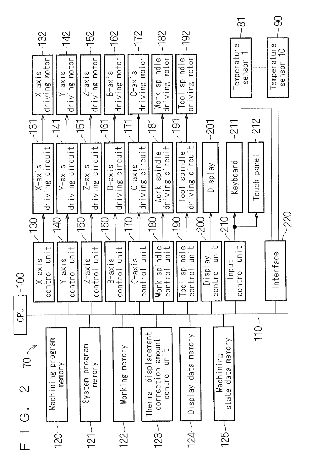
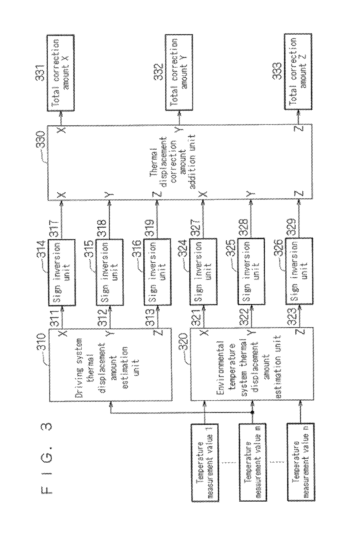
A machine tool includes a workpiece holding unit to hold a workpiece. A tool holding unit holds a tool. At least one of the workpiece holding unit and the tool holding unit is drivingly rotatable or drivingly movable in a predetermined direction to machine the workpiece with the tool. Temperature sensors are attached to members constituting the machine tool. An estimator calculates an environmental temperature system thermal displacement amount due to a heat source outside the machine tool. A correction magnification processor calculates an environmental temperature system thermal displacement correction amount. Another estimator calculates a driving system thermal displacement amount due to a heat source in the machine tool. A thermal displacement correction amount adder obtains and outputs a total thermal displacement correction amount based on which the machine tool performs thermal displacement correction control.

Description

CROSS-REFERENCE TO RELATED APPLICATIONS[0001]The present application is a continuation application of International Application No. PCT / JP2015 / 078588, filed Oct. 8, 2015, which claims priority to Japanese Patent Application No. 2014-220562, filed Oct. 29, 2014. The contents of these applications are incorporated herein by reference in their entirety.BACKGROUND OF THE INVENTION[0002]Field of the Invention[0003]The present invention relates to a machine tool.[0004]Discussion of the Background[0005]A thermal expansion of each of members constituting a machine tool due to heat generated by operating the machine tool and heat from the surroundings of the machine tool is a significant cause that brings the relationship in position between a blade edge of a tool and a machining workpiece to a misaligned state. As a result, the machining accuracy may be deteriorated. Such a misalignment due to heat in the relationship in position between the blade edge of the tool and the machining workpiec...

Claims


Application Information

Patent Timeline
Patent Type & Authority Patents(United States)
IPC IPC(8): G05B19/19G05B19/406G05B19/404B23Q15/04B23Q15/18
CPCG05B19/19B23Q15/04G05B19/404G05B19/406G05B2219/37428G05B2219/37582G05B2219/49102G05B2219/49205G05B2219/49206B23Q15/18G05B2219/49209
Inventor SUZUKI, ATSUSHIISHIDA, TSUNEKAZUOKUDA, TOSHIHITO
Owner YAMAZAKI MAZAK KK
Learn More