
Structural body for shaft, male member, and female member

a structure body and shaft technology, applied in mechanical devices, couplings, transportation and packaging, etc., can solve the problems of tooth-hit noise and unpleasant noise of telescopic shafts, and achieve the effects of reducing sliding resistance, reducing creases, and reducing sliding resistan

Inactive Publication Date: 2019-07-09
NITTA CORP
View PDF34 Cites 3 Cited by
  • Summary
  • Abstract
  • Description
  • Claims
  • Application Information

AI Technical Summary

Benefits of technology

The patent describes a fabric that can be used to improve the fitting between male and female components in a shaft structure. The fabric is stretchy, which allows it to easily conform to the shape of the components. This results in a smooth fitting process and reduces friction between the components. The fabric is made by impregnating it with rubber or resin and then shaping it to match the concave-convex surface of the components. The fabric can be adhered to the components using an adhesive, and there are various methods for manufacturing it. The technical effects of this fabric include improved fitting, reduced friction, and a smooth surface finish.

Problems solved by technology

However, the telescopic shafts generate unpleasant noise, i.e., the so-called tooth-hit noise from between the male and female spline shafts, which are problematic, due to the fact that the dimensional accuracy of such a telescopic shaft is pursued with respect to the splines formed on the outer surface of the male spline shaft or the inner surface of the female spline shaft.

Method used


Image

  • Structural body for shaft, male member, and female member
  • Structural body for shaft, male member, and female member
  • Structural body for shaft, male member, and female member

Examples


modified example 1

[0059]The female component (22) in the above embodiment may be replaced by a female component (32) shown in FIG. 5 ((a) a side view; (b) a view taken along an arrowed line A-A of (a); and (c) a view taken along an arrowed line B-B of (a)). Hereinafter, the female component (32) will be specifically described. Note that, in (a) of FIG. 5, a transparent view is provided only for the parts (32a1, 32a2) by using a dashed-dotted line for convenience in the illustration.

[0060]The female component (32) includes a first hole (32a), a second hole (32b), and a movement stopper (32c) (first movement stopper). The first hole (32a) is configured such that, when a male component like the male component (21) in the above embodiment is inserted into the first hole (32a), the male component slidably fits in the inner peripheral part of the first hole (32a) (e.g., parts 32a1 and 32a2) along the first hole (32a), and the male component is caused by the movement stopper (32c) to stop moving before or a...

modified example 2

[0062]The female component (22) in the above embodiment may be replaced by a female component (42) shown in FIG. 6 ((a) a side view; (b) a view taken along an arrowed line C-C of (a); and (c) a view taken along an arrowed line D-D of (a)). Hereinafter, the female component (42) will be specifically described. Note that, in (a) of FIG. 6, a transparent view is provided only for the parts (42a1, 42a2, 42b1, 42b2) by using a dashed-dotted line for convenience in illustration.

[0063]The female component (42) includes a third hole (42a), a fourth hole (42b), a movement stopper (42c) (second movement stopper), and a movement stopper (42d) (third movement stopper). The third hole (42a) is configured such that, when a male component like the male component (21) in the above embodiment is inserted into the third hole (42a), the male component slidably fits in the inner peripheral part of the third hole (42a) (e.g., parts 42a1 and 42a2) along the third hole (42a), and the male component is cau...


PUM


Abstract

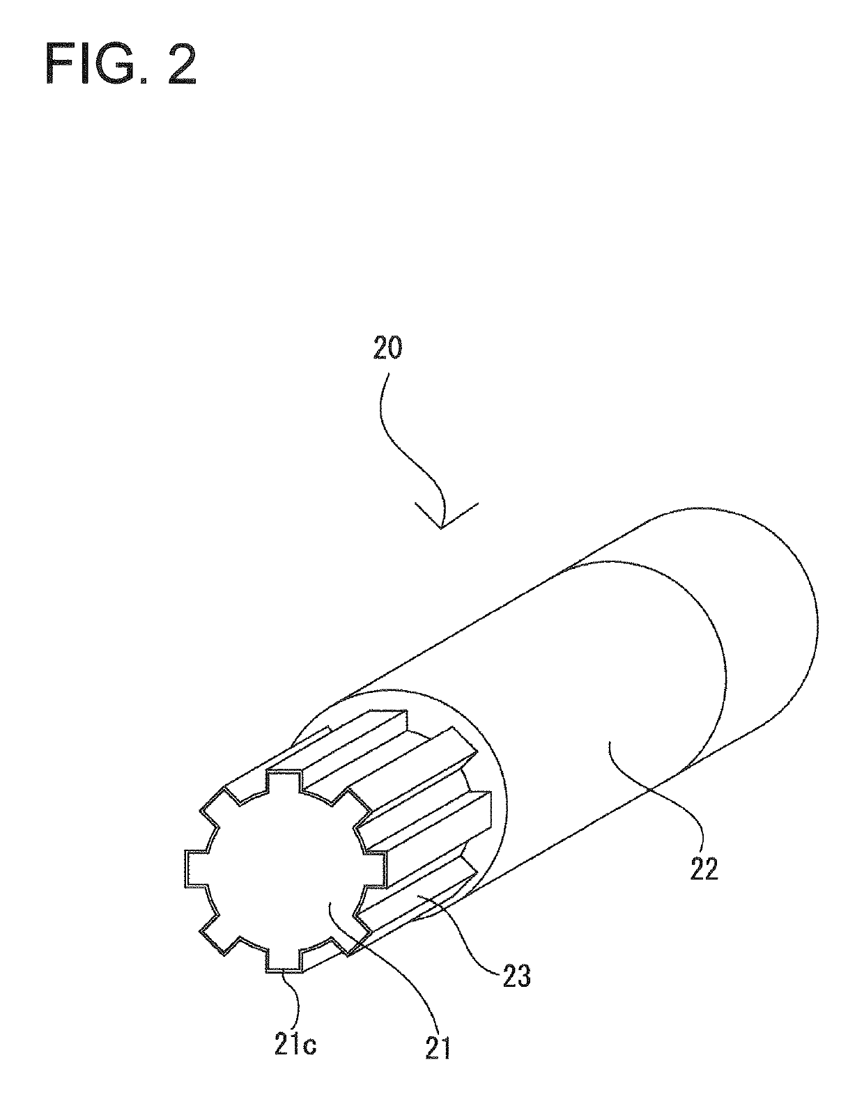
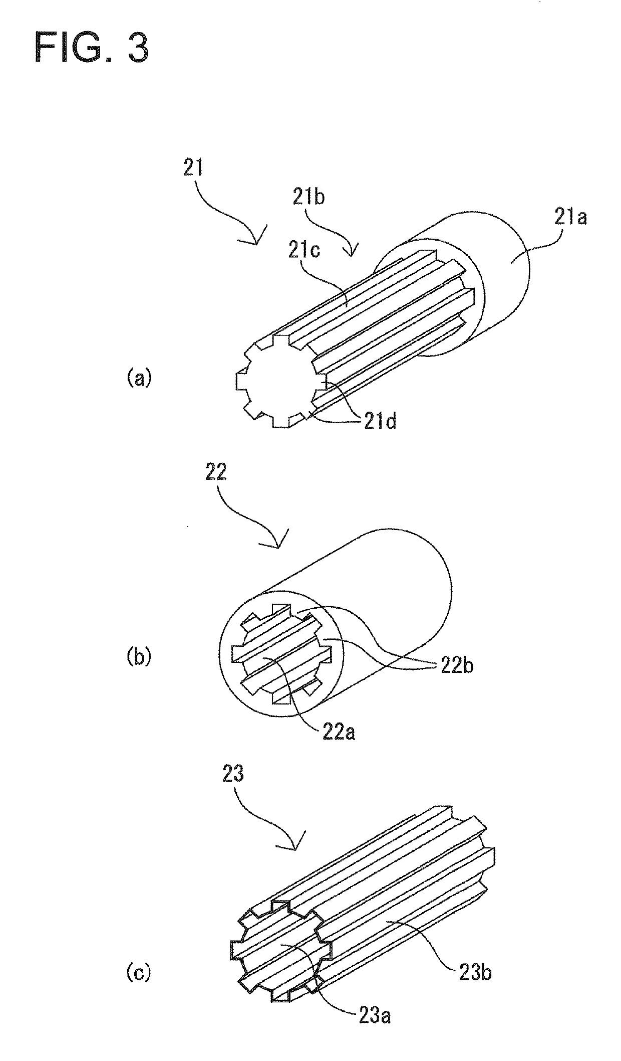
A shaft structure installed in a shaft capable of making a power-transmission, the shaft structure including: a male component having a plurality of male splines formed on an outer peripheral part thereof; and a female component having a plurality of female splines formed on an inner peripheral part thereof, the inner peripheral part configured to allow the outer peripheral part of the male component to be engaged therein so that the male component and the female component can be slidably fitted with respect to each other in an axial direction thereby making up said shaft structure, wherein the outer peripheral part of the male component and the inner peripheral part of the female component have a fabric impregnated with rubber or resin interposed therebetween.

Description

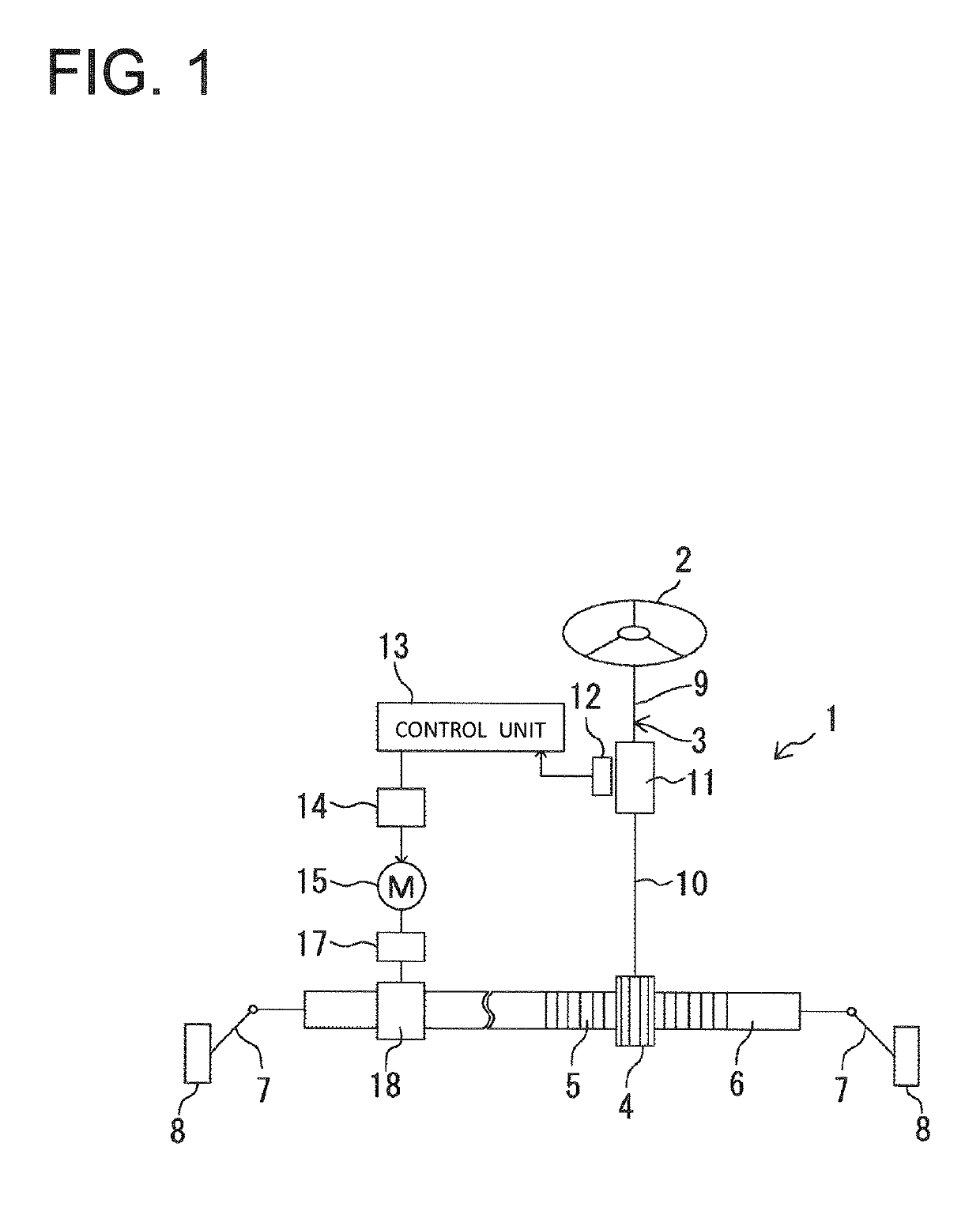
BACKGROUND[0001]Technical Field[0002]The present invention relates to a shaft structure to be installed in shafts used for various industrial machines such as vehicles, and a male component and a female component included in the shaft structure.[0003]Description of the Related Art[0004]Conventionally, there have been publicly well-known telescopic shafts each including male and female spline shafts to be incorporated into, e.g., vehicle steering shafts (see FIG. 2 in Patent Document 1). Such a telescopic shaft has splines formed on an outer surface of the male spline shaft and an inner surface of the female spline shaft. Furthermore, an approximately 0.25 mm thick synthetic resin (nylon or the like) coating is formed on either of the outer surface of the male spline shaft or the inner surface of the female spline shaft.[0005]However, the telescopic shafts generate unpleasant noise, i.e., the so-called tooth-hit noise from between the male and female spline shafts, which are problema...

Claims


Application Information

Patent Timeline
Patent Type & Authority Patents(United States)
IPC IPC(8): F16C3/03F16C29/02B62D1/185F16D1/02F16D3/06
CPCF16C3/03B62D1/185F16C29/02F16D3/06F16D1/02Y10T403/7026F16C2226/80F16D2300/10
Inventor AOKI, KENICHIROKIYOHARA, YOSHIHARUISHIZAKI, YOJINAKAI, KATSUYUKIAOKI, YASUHIROKOJIMA, TOSHIHIKO
Owner NITTA CORP
Learn More