Pulse separated direct inlet axial automotive turbine

a technology of axial turbine and axial inlet, which is applied in the direction of machines/engines, mechanical equipment, cylinders, etc., can solve the problems of not being applicable to systems that use axial turbines, increasing costs, and worse transient response, so as to reduce external emissions and increase the specific power output of engines

Active Publication Date: 2019-06-25
FORD GLOBAL TECH LLC
View PDF14 Cites 0 Cited by
  • Summary
  • Abstract
  • Description
  • Claims
  • Application Information

AI Technical Summary

Benefits of technology

[0001]Turbocharging an internal combustion engine can reduce external emissions and increase the specific power output of the engine, as exhaust departing from the engine cylinders may be directed through a turbine and the resulting energy used to power a compressor. One example configuration integrates the exhaust ports leading from the engine cylinders as well as the turbine housing into the cylinder head itself.
[0002]The inventors herein have recognized that achieving exhaust pulse separation enables an exhaust cam duration beneficial to improving fuel consumption, improving low engine speed torque, and achieving better specific power output that current designs. A turbine integrated into the cylinder head will simultaneously reduce cost and decrease the engine footprint. For example, an integrated turbine may decrease the overall size of the system while increasing the efficiency of the engine and the specific power. An integrated axial turbine may also have a faster transient response than a corresponding radial turbine. However, to maintain efficient combustion with long exhaust cam events, residual exhaust gas must be prevented from entering the engine cylinders during an exhaust blowdown event when multiple exhaust valves are open. This is accomplished with full pulse separation of the exhaust gas up to the point where the exhaust gas enters the turbine. In an I-4 engine with a conventional firing order, for example, this may be accomplished by joining the exhaust ports exiting cylinders 1 and 4 together into a first exhaust duct and joining the exhaust ports exiting cylinders 2 and 3 together into a second exhaust duct. The outlets of the two ducts may be connected to the inlet of the turbine.
[0005]In this way, the system may allow pulse separation of exhaust gas exiting the cylinders all the way to an inlet of a turbine, while maintaining a compact configuration. Separating exhaust gas pulses in this way may result in an increase in the efficiency of exhaust gas delivery to a turbine.
[0008]In another example, a method, comprising combining, in a cylinder head, exhaust gas from inner inline cylinders of an engine to a first semi-circular annular exit, combining, in the cylinder head, exhaust gas from outer inline cylinders of an engine to a second semi-circular annular exit positioned opposite the first semi-circular annular exit, and directing exhaust gas out of the first and second exits through an axial turbine with bearings mounted in the cylinder head. This method may further comprise adjusting a wastegate valve to adjust flow through a wastegate line positioned in the cylinder head. In this way, the flow of exhaust gas may be controlled within the cylinder head to achieve optimal engine performance.

Problems solved by technology

However, the inventors have also recognized that the current manifold designs that achieve full pulse separation are targeted to radial turbines and may not be applicable to systems that use axial turbines.
Incorporating such manifolds may require an external turbocharger, which would increase cost and have a worse transient response.

Method used


Image

  • Pulse separated direct inlet axial automotive turbine
  • Pulse separated direct inlet axial automotive turbine
  • Pulse separated direct inlet axial automotive turbine

Examples


Embodiment Construction

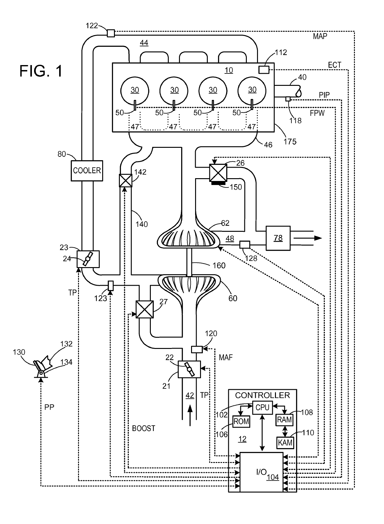
[0019]The following description relates to systems and methods for operating an engine including a turbocharger system, for example as shown in FIG. 1.

[0020]FIG. 1 is a schematic diagram showing an example engine 10, which may be included in a propulsion system of an automobile. The engine 10 includes cylinder head 175, which is shown with four cylinders 30. However, other numbers of cylinders may be used in accordance with the current disclosure. Engine 10 may be controlled at least partially by a control system including controller 12, and by input from a vehicle operator 132 via an input device 130. In this example, input device 130 includes an accelerator pedal and a pedal position sensor 134 for generating a proportional pedal position signal PP. Each combustion chamber (e.g., cylinder) 30 of engine 10 may include combustion chamber walls with a piston (not shown) positioned therein. The pistons may be coupled to a crankshaft 40 so that reciprocating motion of the piston is tra...


PUM


Abstract

Systems and methods for operating a turbocharged engine are described. In one example, a system comprises a cylinder head having a first and second exhaust duct separately coupled to first and second groups of cylinders, each of the first and second exhaust ducts leading to an exhaust driven turbine mounted inside the cylinder head on a bearing, the bearing located within a bearing housing supported by the cylinder head. In this way, exhaust pulses remain separate up to the turbine mounted inside the cylinder head.

Description

BACKGROUND AND SUMMARY[0001]Turbocharging an internal combustion engine can reduce external emissions and increase the specific power output of the engine, as exhaust departing from the engine cylinders may be directed through a turbine and the resulting energy used to power a compressor. One example configuration integrates the exhaust ports leading from the engine cylinders as well as the turbine housing into the cylinder head itself.[0002]The inventors herein have recognized that achieving exhaust pulse separation enables an exhaust cam duration beneficial to improving fuel consumption, improving low engine speed torque, and achieving better specific power output that current designs. A turbine integrated into the cylinder head will simultaneously reduce cost and decrease the engine footprint. For example, an integrated turbine may decrease the overall size of the system while increasing the efficiency of the engine and the specific power. An integrated axial turbine may also hav...

Claims


Application Information

Patent Timeline
Patent Type & Authority Patents(United States)
IPC IPC(8): F02C6/12F02F1/42F01N13/10F02B37/18F02M26/14
CPCF02M26/14F01N13/10F02B37/18F02F1/4264F02C6/12Y02T10/144F02F2001/4278F05D2220/40Y02T10/12
Inventor WADE, ROBERT ANDREWRIEGGER, JOHN CHRISTOPHER
Owner FORD GLOBAL TECH LLC
Why Eureka
Try Eureka