Split cycle reciprocating piston engine

A piston engine, reciprocating technology, applied to internal combustion piston engines, engine components, combustion engines, etc., can solve problems such as large delays, methods that cannot provide energy storage or recovery, and reduction of engine power output rates

Active Publication Date: 2012-01-04
RICARDO UK LTD
View PDF14 Cites 5 Cited by
  • Summary
  • Abstract
  • Description
  • Claims
  • Application Information

AI Technical Summary

Problems solved by technology

This can significantly reduce the rate at which engine power output can be increased, such as when required to accelerate the vehicle, because it introduces a considerable delay in the change in volume supply and charge air pressure from the compression cylinder to the expansion cylinder
Furthermore, although heat exchangers store a finite amount of high pressure compressed air, this is too little to provide the desired means of energy storage or recovery when the vehicle is braking or decelerating

Method used


Image

  • Split cycle reciprocating piston engine
  • Split cycle reciprocating piston engine

Examples


Embodiment Construction

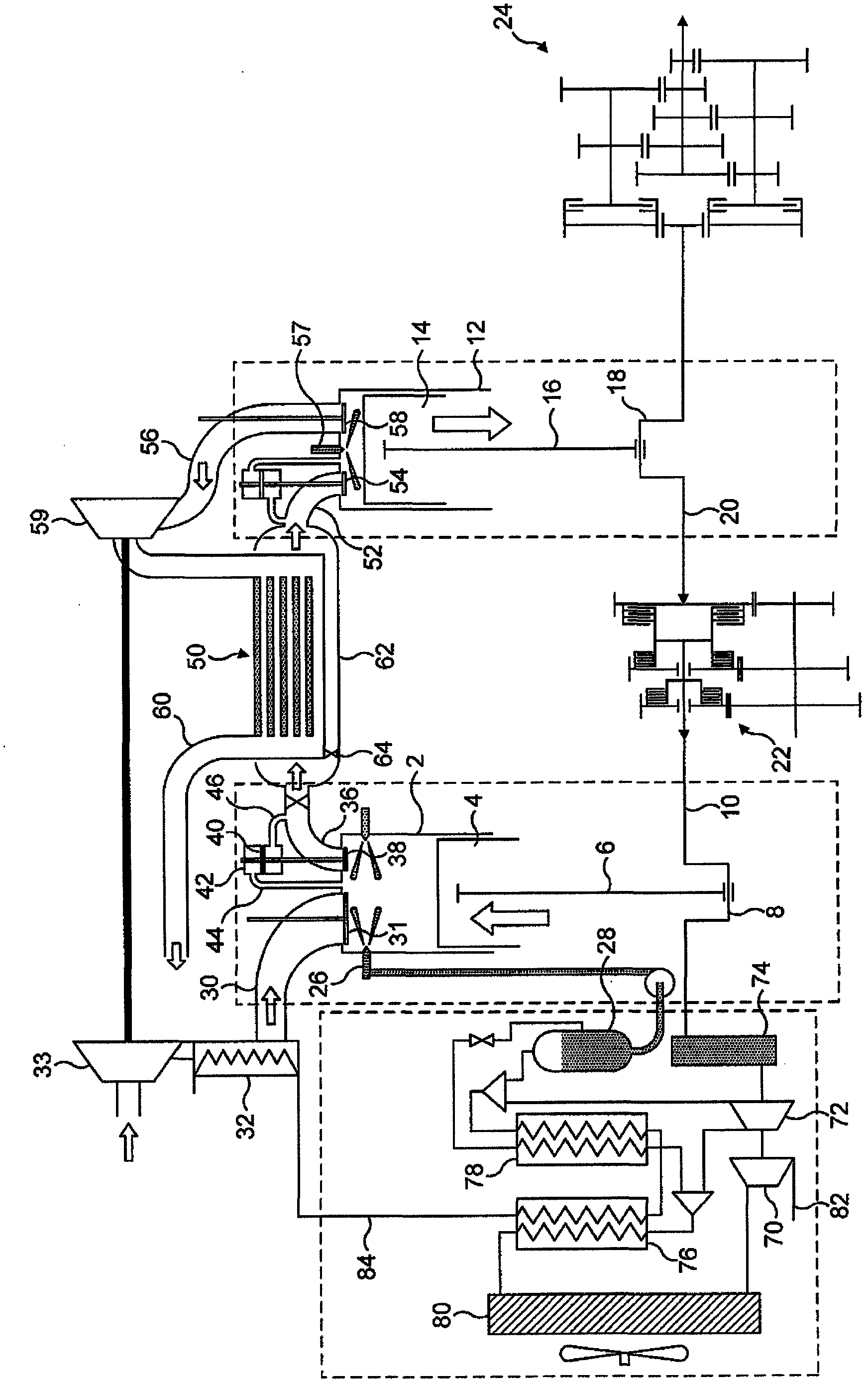
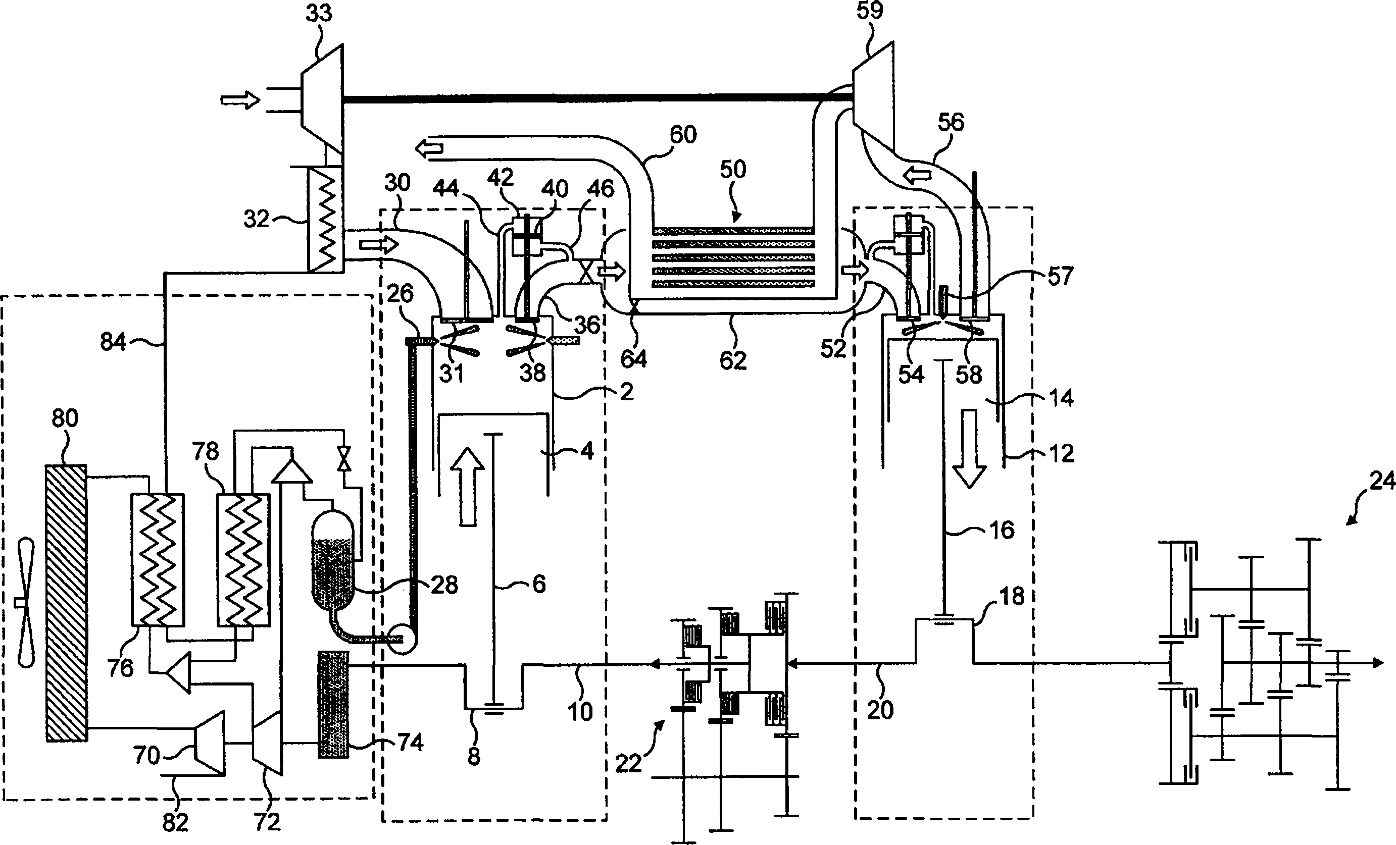
[0019] As shown, the engine comprises a compression cylinder 2 housing a compression piston 4 connected by a connecting rod 6 to a corresponding crank 8 on a portion 10 of the crankshaft. The engine also comprises an expansion cylinder 12 housing an expansion piston 14 connected by a connecting rod 16 to a corresponding crank 18 on another part 20 of the crankshaft. Although only one compression cylinder 2 and one expansion cylinder 12 are shown, it should be understood that there may be any desired number of such cylinders and that furthermore the number of compression cylinders need not be the same as the number of expansion cylinders, and that the dimensions of the two types of cylinders It doesn't have to be the same either. The two parts 10, 20 of the crankshaft are not integrally connected together to rotate at the same speed as conventional, but are connected by a transmission or gearbox 22 with optionally variable ratios. The crankshaft 10, 20 is also connected to a t...


PUM


Abstract

A split cycle reciprocating piston engine includes a compression cylinder (2) accommodating a compression piston (4) and an expansion cylinder (12) accommodating an expansion piston (14). The compression cylinder (2) has an inlet port (30) for the admission of air and an outlet port (36) which communicates with a first path of a heat exchanger (5). The expansion cylinder (12) has an inlet port (52), which communicates with the first path of the heat exchanger (5), and an outlet port (56), which communicates with a second path of the heat exchanger (5) in heat exchange relationship with the first path. The method of operating the engine includes injecting a liquefied, non-oxidising, non-combustible gas, such as nitrogen, into the compression cylinder (2).

Description

technical field [0001] This invention relates to split cycle reciprocating piston engines and is related to the type of engine known as isothermal compression isobaric combustion. More specifically, the present invention relates to a method of operating a split-cycle reciprocating piston engine comprising a compression cylinder housing a compression piston, an expansion cylinder housing an expansion piston, the compression cylinder having an inlet for admitting air, and a The outlet communicated with the first path of the heat exchanger, the expansion cylinder has an inlet communicated with the first path of the heat exchanger and an outlet communicated with the second path of the heat exchanger, the second path is in a heat exchange relationship with the first path, the The method involves spraying liquid into a compression cylinder. Background technique [0002] Such engines are known and disclosed, for example, in WO 07 / 081445. [0003] In a conventional internal combus...

Claims


Application Information

Patent Timeline
IPC IPC(8): F02B41/06F02B47/04F02M25/00
CPCF02B47/04F02B47/02F02B41/06F02B43/10Y02T10/121Y02T10/32F02M25/00F02B29/0406F02M25/03F25J1/0012F25J1/0015F25J1/0017F25J1/0037F25J1/0201F25J1/0228F25J2210/40F25J2230/22F25J2230/30F25J2240/80F25J2260/42F25J2260/50Y02T10/12Y02T10/30
Inventor N·S·杰克逊A·F·阿特金
Owner RICARDO UK LTD
Why Eureka
Try Eureka