Strategy for engine cold start emission reduction

Active Publication Date: 2014-08-28
FORD GLOBAL TECH LLC
View PDF6 Cites 4 Cited by
  • Summary
  • Abstract
  • Description
  • Claims
  • Application Information

AI Technical Summary

Benefits of technology

The patent text describes a method for reducing emissions and increasing power output in an internal combustion engine by integrating an exhaust manifold and using cooling to decrease the time required for emission control devices to reach their operating temperature. The technical effect of this method is to decrease engine emissions during cold starts and to improve engine performance. The patent also describes an engine system that allows for better control over the temperature of the cylinder head by circulating coolant during certain conditions and draining it during others. Overall, the patent focuses on improving the performance and reducing emissions of internal combustion engines.

Problems solved by technology

This may in turn increase engine emissions at cold start in the period of time before the emission control device has reached a predetermined operating temperature.

Method used


Image

  • Strategy for engine cold start emission reduction
  • Strategy for engine cold start emission reduction
  • Strategy for engine cold start emission reduction

Examples


Embodiment Construction

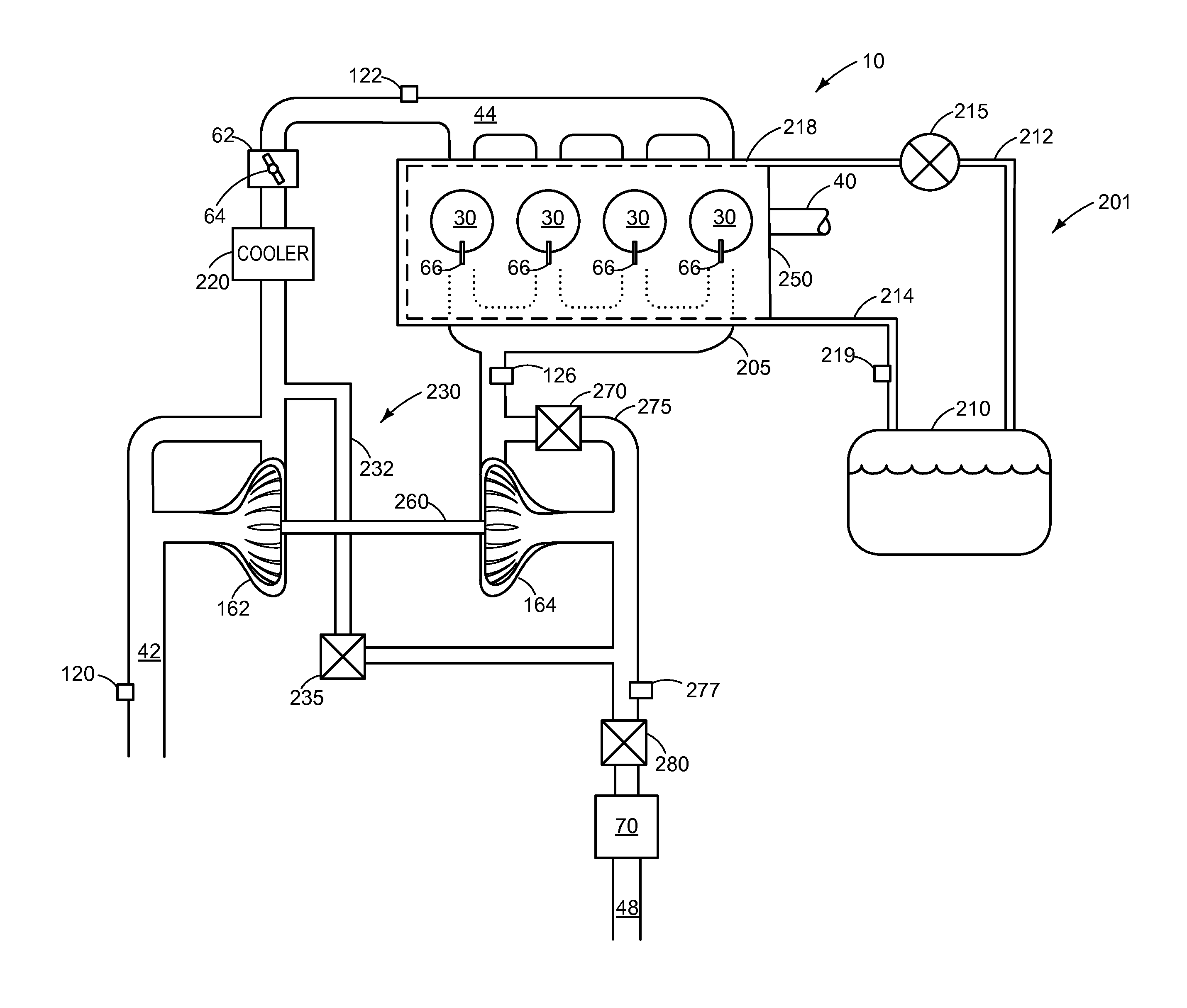
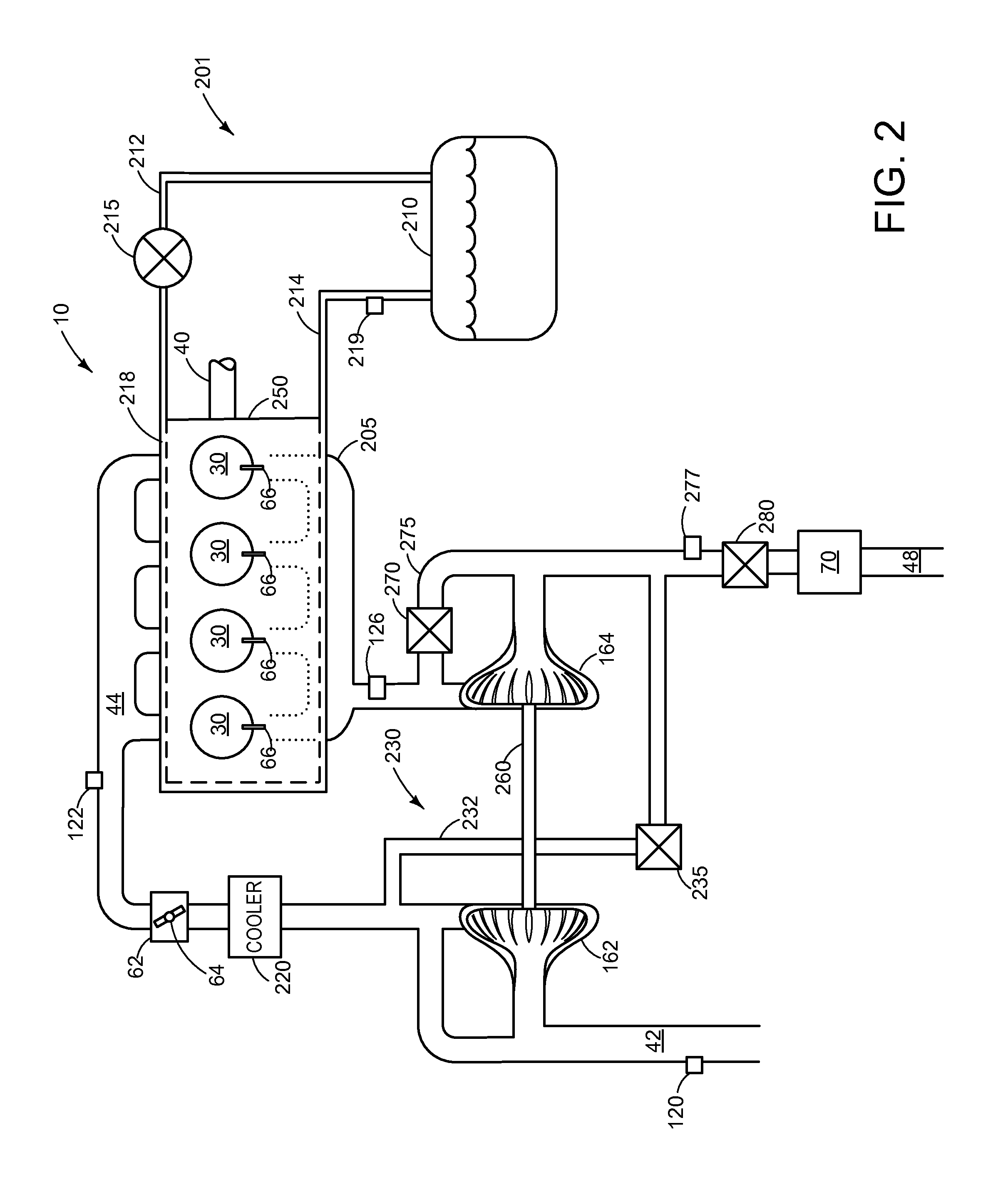
[0011]The present description relates to systems and methods for operating an internal combustion engine at a cold-start condition. In one non-limiting example, the engine may be configured as illustrated in FIG. 1. Further, additional components of an engine exhaust system as illustrated in FIG. 2 may be part of the engine of FIG. 1. A cold-start routine may be provided by the system illustrated in FIG. 2 and the method illustrated in FIG. 3, which shows an example method for operating an engine at a cold-start condition.

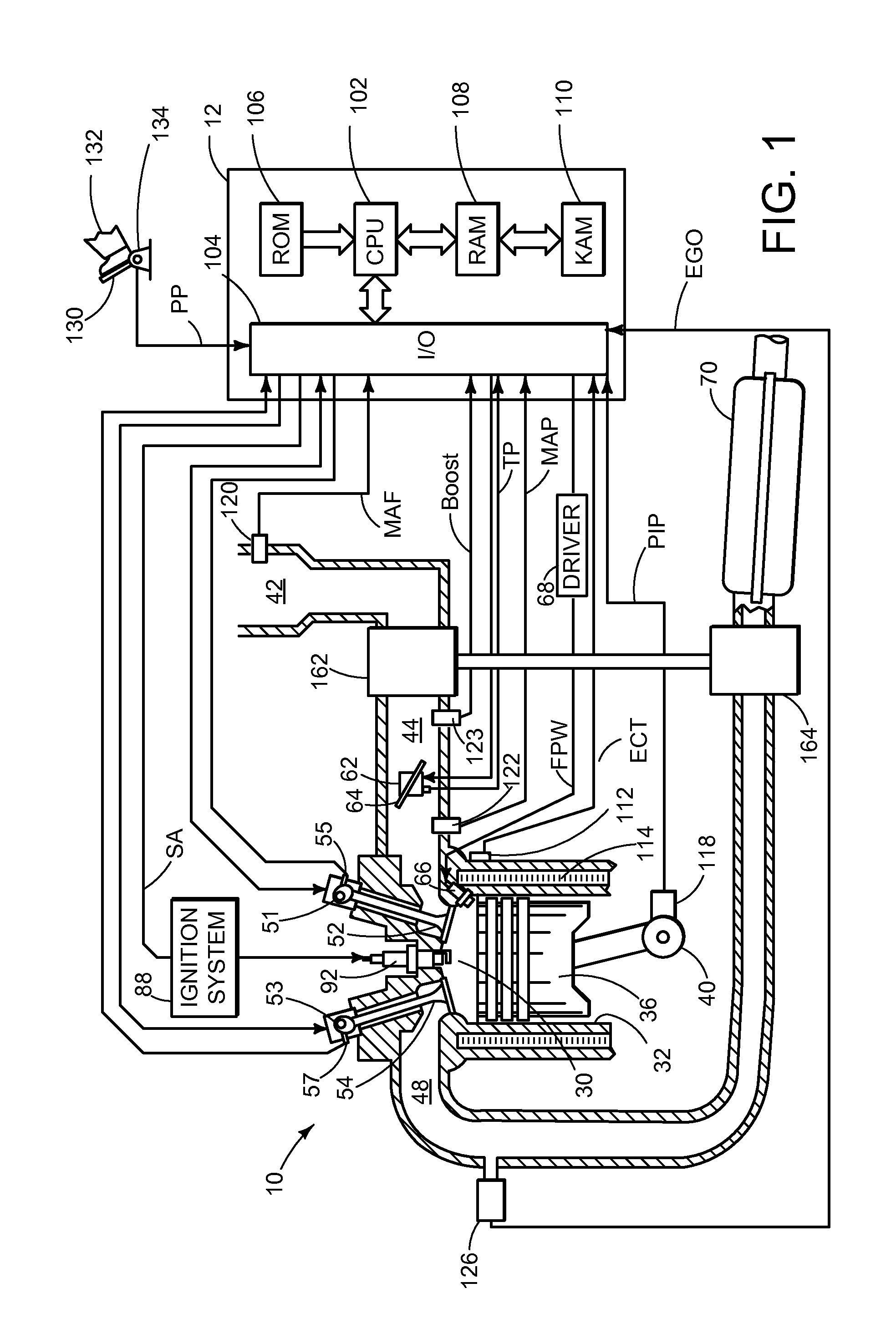
[0012]FIG. 1 is a schematic diagram showing one cylinder of multi-cylinder engine 10, which may be included in a propulsion system of an automobile. Engine 10 may be controlled at least partially by a control system including controller 12 and by input from a vehicle operator 132 via an input device 130. In this example, input device 130 includes an accelerator pedal and a pedal position sensor 134 for generating a proportional pedal position signal PP. Combustion ...


PUM


Abstract

A method for operating an engine having a cylinder head, comprising: following light-off of an exhaust catalyst from a cold-start condition, circulating liquid coolant through a cooling jacket of the cylinder head, and at a subsequent engine-off condition, draining at least some of the liquid coolant from the cooling jacket. In this way, at a cold start condition, the cooling jacket of the cylinder head may be filled with air, thus decreasing the amount of time needed for the exhaust catalyst to reach a light-off temperature.

Description

BACKGROUND AND SUMMARY[0001]Turbocharging an internal combustion engine can both reduce external emissions and increase the specific power output of the engine, as exhaust from the engine cylinders may be directed through a turbine and the resulting kinetic energy used to power a compressor. One example configuration integrates the exhaust manifolds leading from the engine cylinders to the turbine into the cylinder head itself, referred to as an integrated exhaust manifold.[0002]The integrated exhaust manifold configuration may conserve heat energy from the exhaust gas, which may be transferred to the surrounding material of the cylinder head. This may in turn require cooling the cylinder head during normal engine operating conditions. In one example, liquid coolant may be circulated through chambers in the cylinder head, lowering the temperature of the cylinder head material and / or the exhaust gas exiting the exhaust manifold.[0003]However, exhaust emission control devices, such as...

Claims


Application Information

Patent Timeline
IPC IPC(8): F02F1/10
CPCF02F1/10F01P11/0276F01P2003/024F01P2037/02
Inventor ZHANG, XIAOGANG
Owner FORD GLOBAL TECH LLC
Why Eureka
Try Eureka